
Instruction Manual
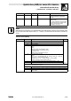
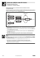
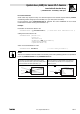
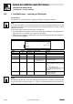
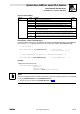
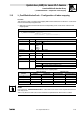
Table Of Contents
- System bus (CAN) for Lenze PLC devices
- This documentation is valid for ...
- Contents
- 1 Preface and general information
- 2 General information on the system bus (CAN)
- 2.1 Introduction
- 2.2 Interfaces of the Lenze PLCs for system bus connection
- 2.3 Identification of the nodes
- 2.4 Structure of the CAN telegram
- 2.5 Network management (NMT)
- 2.6 Transmission of process data
- 2.7 Transmitting parameter data
- 2.8 Free CAN objects
- 2.9 Application recommendations for the different CAN objects
- 2.10 Monitoring mechanisms
- 3 Configuration (system bus - CAN interface)
- 3.1 CAN baud rate
- 3.2 CAN boot-up
- 3.3 Node address (node ID)
- 3.4 Identifiers of the process data objects
- 3.5 Cycle time (CAN2_OUT/CAN3_OUT)
- 3.6 Delay time (CAN2_OUT/CAN3_OUT)
- 3.7 Synchronisation
- 3.8 Reset node
- 3.9 System bus management
- 3.10 Mapping indexes to codes
- 3.11 Remote parameterisation (gateway function)
- 3.12 Monitoring processes
- 3.13 Diagnostics
- 4 Configuration (AIF interface)
- 5 Configuration (FIF interface)
- 6 Configuration (CAN-AUX system bus interface)
- 7 CAN system blocks
- 8 FIF-CAN system blocks (only Drive PLC)
- 9 CAN-AUX system blocks (only ECSxA)
- 10 LenzeCanDrv.lib function library
- 10.1 Overview
- 10.2 Version identifiers of the function library
- 10.3 L_CanInit - initialising the CAN driver
- 10.4 L_CanClose - deactivating the CAN driver
- 10.5 L_CanGetStatus - querying the driver status
- 10.6 L_CanGetRelocCobId - querying the COB-ID range
- 10.7 L_CanPdoTransmit - transmitting a CAN object
- 10.8 L_CanPdoReceive - receiving a CAN object
- 11 LenzeCanDSxDrv.libfunction library
- 11.1 Overview
- 11.2 Version identifiers of the function library
- 11.3 L_CanDSxInitIndexCode - Configuration of index mapping
- 11.4 L_CanDSxOpen - initialising the CanDSx driver
- 11.5 L_CanDSxClose - deactivating the index mapping
- 11.6 L_CanDSxOpenHeartBeat - initialising a "Heartbeat"
- 11.7 L_CanDSxHeartBeat - carrying out a "Heartbeat"
- 11.8 L_CanDSxCloseHeartBeat - deactivating the "Heartbeat"
- 11.9 L_CanDSxOpenNodeGuarding - initialising the "Node Guarding"
- 11.10 L_CanDSxNodeGuarding - carrying out a "Node guarding"
- 11.11 L_CanDSxCloseNodeGuarding - deactivating the "Node Guarding"
- 12 Index
System bus (CAN) for Lenze PLC devices
LenzeCanDrv.lib function library
10.8 L_CanPdoReceive − receiving a CAN object
10−13
L
PLC−Systembus EN 2.0
Receive status (nState)
Data type Value Meaning Priority
Integer
−150 CAN bus is not in the Operational state. 1 (high)
−121 Incorrect driver number (wDrvNr) 2
−120 Driver not initialised 3
−12 The set message identifier (COB−ID) is beyond the permissible range (0 ... 2047). 4
−11 Pointer pIOAdress does not point to PLC−RAM. 5 (low)
* If there are several error causes, always the value associated with the error cause
of the highest priority is returned.
0 Data have been faultlessly received.
10 The specification for the telegram length byLen is higher than 8. The telegram length has been
limited to 8 bytes.
200 Data were received without resetting bNewMessage. Therefore valid data were possibly overwritten
in the receive memory.
Resetting the variable "bNewMessage"
If data have been received from the CAN bus, the output variable bNewMessage is set to TRUE and
only is reset to FALSE again by calling the action <Instance name>.ResetNewMessage:
(* FB instance *)
ReceiveFromID678: L_CanPdoReceive; (* receive data *)
(* from identifier 678 *)
...
(* reset NewMessage information at FB ReceiveFromID678 *)
ReceiveFromID678.ResetNewMessage; (* reset NewMessage *)
Example
Calling the function block in ST:
ReceiveFromID678(wDrvNr:=10,
byLen:=8,
dwCobID:=678,
pIOAdress:=ADR(abyReceiveData);
Note!
The use of an address which is stored in the memory area of the operating system is not permitted
for the L_CanPdoTransmit and L_CanPdoReceiveFBs!
· See also note to the function L_CanPdoTransmit. (^ 10−8)