
Instruction Manual
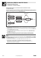
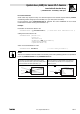
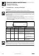
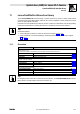
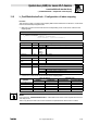
Table Of Contents
- System bus (CAN) for Lenze PLC devices
- This documentation is valid for ...
- Contents
- 1 Preface and general information
- 2 General information on the system bus (CAN)
- 2.1 Introduction
- 2.2 Interfaces of the Lenze PLCs for system bus connection
- 2.3 Identification of the nodes
- 2.4 Structure of the CAN telegram
- 2.5 Network management (NMT)
- 2.6 Transmission of process data
- 2.7 Transmitting parameter data
- 2.8 Free CAN objects
- 2.9 Application recommendations for the different CAN objects
- 2.10 Monitoring mechanisms
- 3 Configuration (system bus - CAN interface)
- 3.1 CAN baud rate
- 3.2 CAN boot-up
- 3.3 Node address (node ID)
- 3.4 Identifiers of the process data objects
- 3.5 Cycle time (CAN2_OUT/CAN3_OUT)
- 3.6 Delay time (CAN2_OUT/CAN3_OUT)
- 3.7 Synchronisation
- 3.8 Reset node
- 3.9 System bus management
- 3.10 Mapping indexes to codes
- 3.11 Remote parameterisation (gateway function)
- 3.12 Monitoring processes
- 3.13 Diagnostics
- 4 Configuration (AIF interface)
- 5 Configuration (FIF interface)
- 6 Configuration (CAN-AUX system bus interface)
- 7 CAN system blocks
- 8 FIF-CAN system blocks (only Drive PLC)
- 9 CAN-AUX system blocks (only ECSxA)
- 10 LenzeCanDrv.lib function library
- 10.1 Overview
- 10.2 Version identifiers of the function library
- 10.3 L_CanInit - initialising the CAN driver
- 10.4 L_CanClose - deactivating the CAN driver
- 10.5 L_CanGetStatus - querying the driver status
- 10.6 L_CanGetRelocCobId - querying the COB-ID range
- 10.7 L_CanPdoTransmit - transmitting a CAN object
- 10.8 L_CanPdoReceive - receiving a CAN object
- 11 LenzeCanDSxDrv.libfunction library
- 11.1 Overview
- 11.2 Version identifiers of the function library
- 11.3 L_CanDSxInitIndexCode - Configuration of index mapping
- 11.4 L_CanDSxOpen - initialising the CanDSx driver
- 11.5 L_CanDSxClose - deactivating the index mapping
- 11.6 L_CanDSxOpenHeartBeat - initialising a "Heartbeat"
- 11.7 L_CanDSxHeartBeat - carrying out a "Heartbeat"
- 11.8 L_CanDSxCloseHeartBeat - deactivating the "Heartbeat"
- 11.9 L_CanDSxOpenNodeGuarding - initialising the "Node Guarding"
- 11.10 L_CanDSxNodeGuarding - carrying out a "Node guarding"
- 11.11 L_CanDSxCloseNodeGuarding - deactivating the "Node Guarding"
- 12 Index
System bus (CAN) for Lenze PLC devices
LenzeCanDSxDrv.lib function library
11.1 Overview
11−1
L
PLC−Systembus EN 2.0
11 LenzeCanDSxDrv.libfunction library
The LenzeCanDSxDrv.lib function library contains functions by means of which CAN indexes
received via the system bus interface within the PLC can be "mapped" to other codes than to those
which are automatically allocated.
Furthermore functions/FBs are provided, by means of which the "Heartbeat" and "Node guarding"
monitoring mechanisms for ensuring the function of system bus nodes can be realised.
Tip!
General information
· on the mapping of indexes to codes can be found in chapter 3.10. (^ 3−8)
· on the "Heartbeat" and "Node Guarding" monitoring mechanisms can be found in chapter
2.10.
(^ 2−21)
11.1 Overview
Function/FB Information
Mapping indexes to codes
· The functions are limited to the parameter access via the system bus interface integrated in the PLC.
L_CanDSxInitIndexCode Configure index mapping ^ 11−3
L_CanDSxOpen Activate index mapping ^ 11−5
L_CanDSxClose Deactivate index mapping again ^ 11−6
"Hearbeat" monitoring mechanism
L_CanDSxOpenHeartBeat Initialise "Heartbeat" ^ 11−7
L_CanDSxHeartBeat Carry out "Heartbeat" ^ 11−8
L_CanDSxCloseHeartBeat Deactivate "Heartbeat" again ^ 11−10
"Node guarding" monitoring mechanism
L_CanDSxOpenNodeGuarding Initialise "Node guarding" ^ 11−11
L_CanDSxNodeGuarding Carry out "Node guarding" ^ 11−12
L_CanDSxCloseNodeGuarding Deactivate "Node guarding" again ^ 11−15
Tip!
For mapping codes which are accessed via the AIF interface, the LenzeAifParMapDrv.lib function
library with its corresponding functions is provided to you.