
Instruction Manual
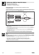
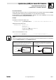
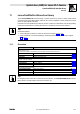
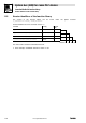
Table Of Contents
- System bus (CAN) for Lenze PLC devices
- This documentation is valid for ...
- Contents
- 1 Preface and general information
- 2 General information on the system bus (CAN)
- 2.1 Introduction
- 2.2 Interfaces of the Lenze PLCs for system bus connection
- 2.3 Identification of the nodes
- 2.4 Structure of the CAN telegram
- 2.5 Network management (NMT)
- 2.6 Transmission of process data
- 2.7 Transmitting parameter data
- 2.8 Free CAN objects
- 2.9 Application recommendations for the different CAN objects
- 2.10 Monitoring mechanisms
- 3 Configuration (system bus - CAN interface)
- 3.1 CAN baud rate
- 3.2 CAN boot-up
- 3.3 Node address (node ID)
- 3.4 Identifiers of the process data objects
- 3.5 Cycle time (CAN2_OUT/CAN3_OUT)
- 3.6 Delay time (CAN2_OUT/CAN3_OUT)
- 3.7 Synchronisation
- 3.8 Reset node
- 3.9 System bus management
- 3.10 Mapping indexes to codes
- 3.11 Remote parameterisation (gateway function)
- 3.12 Monitoring processes
- 3.13 Diagnostics
- 4 Configuration (AIF interface)
- 5 Configuration (FIF interface)
- 6 Configuration (CAN-AUX system bus interface)
- 7 CAN system blocks
- 8 FIF-CAN system blocks (only Drive PLC)
- 9 CAN-AUX system blocks (only ECSxA)
- 10 LenzeCanDrv.lib function library
- 10.1 Overview
- 10.2 Version identifiers of the function library
- 10.3 L_CanInit - initialising the CAN driver
- 10.4 L_CanClose - deactivating the CAN driver
- 10.5 L_CanGetStatus - querying the driver status
- 10.6 L_CanGetRelocCobId - querying the COB-ID range
- 10.7 L_CanPdoTransmit - transmitting a CAN object
- 10.8 L_CanPdoReceive - receiving a CAN object
- 11 LenzeCanDSxDrv.libfunction library
- 11.1 Overview
- 11.2 Version identifiers of the function library
- 11.3 L_CanDSxInitIndexCode - Configuration of index mapping
- 11.4 L_CanDSxOpen - initialising the CanDSx driver
- 11.5 L_CanDSxClose - deactivating the index mapping
- 11.6 L_CanDSxOpenHeartBeat - initialising a "Heartbeat"
- 11.7 L_CanDSxHeartBeat - carrying out a "Heartbeat"
- 11.8 L_CanDSxCloseHeartBeat - deactivating the "Heartbeat"
- 11.9 L_CanDSxOpenNodeGuarding - initialising the "Node Guarding"
- 11.10 L_CanDSxNodeGuarding - carrying out a "Node guarding"
- 11.11 L_CanDSxCloseNodeGuarding - deactivating the "Node Guarding"
- 12 Index
System bus (CAN) for Lenze PLC devices
LenzeCanDSxDrv.lib function library
11.3 L_CanDSxInitIndexCode − Configuration of index mapping
11−3
L
PLC−Systembus EN 2.0
11.3 L_CanDSxInitIndexCode − Configuration of index mapping
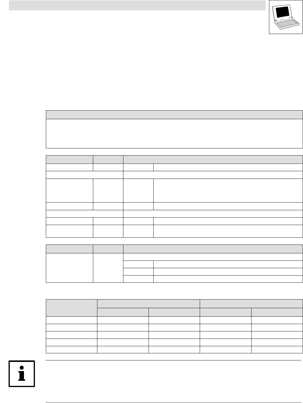
Function
This function is used to configure the mapping table and the redirection of indeces to codes other
than the automatically assigned codes.
· With every function call one index and the corresponding Lenze code can be entered in the
mapping table.
Declaration
INT L_CanDSxInitIndexCode (byTabIndex,
wCANIndex, byCANSubIndex,
wLenzeCodeNumber, byLenzeSubCodeNumber);
Transfer parameters Data type Information/possible settings
byTabIndex Byte 0 ... 255 Number of the configuration entry in the mapping table.
Index to be redirected:
wCANIndex Word 1000
hex
...
8FFF
hex
(4096
dec
...
36863
dec
)
CAN index
byCANSubIndex Byte 0 ... 255 CAN subindex
Redirection target (Lenze code):
wLenzeCodeNumber Word 1 ... 7999 Code number
byLenzeSubCode
Number
Byte 0 ... 255 Subcode number
Return value Data type Value/meaning
Integer Status
0 Entry in the mapping table has been successful.
−20 Error: Transfer parameter wCANIndex is invalid.
−30 Error: Transfer parameter wLenzeCodeNumber is invalid.
· A maximum of 256 entries can be entered in the mapping table:
Code to be redirected Redirection target
byTabIndex
wCANIndex byCANSubIndex wLenzeCodeNumber byLenzeSubCodeNumber
0
1 4104 2 3200 5
2
...
255
Note!
If the function L_CanDSxInitIndexCode is called while code read or write requests are active an
error may occur!
This is why all actions with code access should be completed before this function is called.