
Instruction Manual
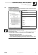
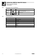

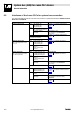
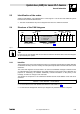
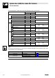
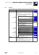
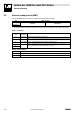
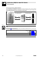
Table Of Contents
- System bus (CAN) for Lenze PLC devices
- This documentation is valid for ...
- Contents
- 1 Preface and general information
- 2 General information on the system bus (CAN)
- 2.1 Introduction
- 2.2 Interfaces of the Lenze PLCs for system bus connection
- 2.3 Identification of the nodes
- 2.4 Structure of the CAN telegram
- 2.5 Network management (NMT)
- 2.6 Transmission of process data
- 2.7 Transmitting parameter data
- 2.8 Free CAN objects
- 2.9 Application recommendations for the different CAN objects
- 2.10 Monitoring mechanisms
- 3 Configuration (system bus - CAN interface)
- 3.1 CAN baud rate
- 3.2 CAN boot-up
- 3.3 Node address (node ID)
- 3.4 Identifiers of the process data objects
- 3.5 Cycle time (CAN2_OUT/CAN3_OUT)
- 3.6 Delay time (CAN2_OUT/CAN3_OUT)
- 3.7 Synchronisation
- 3.8 Reset node
- 3.9 System bus management
- 3.10 Mapping indexes to codes
- 3.11 Remote parameterisation (gateway function)
- 3.12 Monitoring processes
- 3.13 Diagnostics
- 4 Configuration (AIF interface)
- 5 Configuration (FIF interface)
- 6 Configuration (CAN-AUX system bus interface)
- 7 CAN system blocks
- 8 FIF-CAN system blocks (only Drive PLC)
- 9 CAN-AUX system blocks (only ECSxA)
- 10 LenzeCanDrv.lib function library
- 10.1 Overview
- 10.2 Version identifiers of the function library
- 10.3 L_CanInit - initialising the CAN driver
- 10.4 L_CanClose - deactivating the CAN driver
- 10.5 L_CanGetStatus - querying the driver status
- 10.6 L_CanGetRelocCobId - querying the COB-ID range
- 10.7 L_CanPdoTransmit - transmitting a CAN object
- 10.8 L_CanPdoReceive - receiving a CAN object
- 11 LenzeCanDSxDrv.libfunction library
- 11.1 Overview
- 11.2 Version identifiers of the function library
- 11.3 L_CanDSxInitIndexCode - Configuration of index mapping
- 11.4 L_CanDSxOpen - initialising the CanDSx driver
- 11.5 L_CanDSxClose - deactivating the index mapping
- 11.6 L_CanDSxOpenHeartBeat - initialising a "Heartbeat"
- 11.7 L_CanDSxHeartBeat - carrying out a "Heartbeat"
- 11.8 L_CanDSxCloseHeartBeat - deactivating the "Heartbeat"
- 11.9 L_CanDSxOpenNodeGuarding - initialising the "Node Guarding"
- 11.10 L_CanDSxNodeGuarding - carrying out a "Node guarding"
- 11.11 L_CanDSxCloseNodeGuarding - deactivating the "Node Guarding"
- 12 Index
System bus (CAN) for Lenze PLC devices
General information
2−4
l
PLC−Systembus EN 2.0
The following table contains the preset basic identifiers of the Lenze devices:
Identifier = basic identifier + node address of the node
dec hex
·Network management
Tx (transmission) 0 0
Rx (reception) 0 0
Sync telegram
Tx (transmission) 128 80
Rx (reception) 128 80
SDOs Parameter data channel 1
Output (transmission) 1536 600
+ C0350
+ C2350
+ C2450
(CAN)
(XCAN)
(FIF−CAN/CAN−AUX)
Input (reception) 1408 580
Parameter data channel 2
Output (transmission) 1600 640
+ C0350
+ C2350
+ C2450
(CAN)
(XCAN)
(FIF−CAN/CAN−AUX)
Input (reception) 1472 5C0
PDOs CAN1_IO (cyclic process data)
CAN1_IN 512 200
+ C0350
+ C2350
+ C2450
(CAN)
(XCAN)
(FIF−CAN/CAN−AUX)
CAN1_OUT 384 180
CAN2_IO (event− or time−controlled process data)
CAN2_IN 640 280
+ C0350
+ C2350
+ C2450
(CAN)
(XCAN)
(FIF−CAN/CAN−AUX)
CAN2_OUT 641 281
CAN3_IO (event− or time−controlled process data)
CAN3_IN 768 300
+ C0350
+ C2350
+ C2450
(CAN)
(XCAN)
(FIF−CAN/CAN−AUX)
CAN3_OUT 769 301
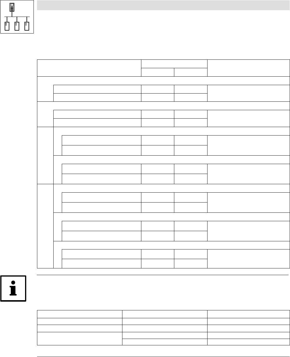
Tip!
For the process data objects you can also set an individual identifier via the following codes, which
is independent of the node address:
Code Interface Information
C0353 / C0354 CAN (system bus interface) ^ 3−4
C2353 / C2354 XCAN (AIF interface) ^ 4−4
C2453 / C2454
FIF−CAN (FIF interface) ^ 5−4
CAN−AUX (system bus interface) ^ 6−4