
Instruction Manual
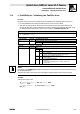
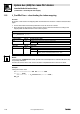
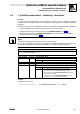
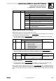
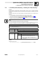

Table Of Contents
- System bus (CAN) for Lenze PLC devices
- This documentation is valid for ...
- Contents
- 1 Preface and general information
- 2 General information on the system bus (CAN)
- 2.1 Introduction
- 2.2 Interfaces of the Lenze PLCs for system bus connection
- 2.3 Identification of the nodes
- 2.4 Structure of the CAN telegram
- 2.5 Network management (NMT)
- 2.6 Transmission of process data
- 2.7 Transmitting parameter data
- 2.8 Free CAN objects
- 2.9 Application recommendations for the different CAN objects
- 2.10 Monitoring mechanisms
- 3 Configuration (system bus - CAN interface)
- 3.1 CAN baud rate
- 3.2 CAN boot-up
- 3.3 Node address (node ID)
- 3.4 Identifiers of the process data objects
- 3.5 Cycle time (CAN2_OUT/CAN3_OUT)
- 3.6 Delay time (CAN2_OUT/CAN3_OUT)
- 3.7 Synchronisation
- 3.8 Reset node
- 3.9 System bus management
- 3.10 Mapping indexes to codes
- 3.11 Remote parameterisation (gateway function)
- 3.12 Monitoring processes
- 3.13 Diagnostics
- 4 Configuration (AIF interface)
- 5 Configuration (FIF interface)
- 6 Configuration (CAN-AUX system bus interface)
- 7 CAN system blocks
- 8 FIF-CAN system blocks (only Drive PLC)
- 9 CAN-AUX system blocks (only ECSxA)
- 10 LenzeCanDrv.lib function library
- 10.1 Overview
- 10.2 Version identifiers of the function library
- 10.3 L_CanInit - initialising the CAN driver
- 10.4 L_CanClose - deactivating the CAN driver
- 10.5 L_CanGetStatus - querying the driver status
- 10.6 L_CanGetRelocCobId - querying the COB-ID range
- 10.7 L_CanPdoTransmit - transmitting a CAN object
- 10.8 L_CanPdoReceive - receiving a CAN object
- 11 LenzeCanDSxDrv.libfunction library
- 11.1 Overview
- 11.2 Version identifiers of the function library
- 11.3 L_CanDSxInitIndexCode - Configuration of index mapping
- 11.4 L_CanDSxOpen - initialising the CanDSx driver
- 11.5 L_CanDSxClose - deactivating the index mapping
- 11.6 L_CanDSxOpenHeartBeat - initialising a "Heartbeat"
- 11.7 L_CanDSxHeartBeat - carrying out a "Heartbeat"
- 11.8 L_CanDSxCloseHeartBeat - deactivating the "Heartbeat"
- 11.9 L_CanDSxOpenNodeGuarding - initialising the "Node Guarding"
- 11.10 L_CanDSxNodeGuarding - carrying out a "Node guarding"
- 11.11 L_CanDSxCloseNodeGuarding - deactivating the "Node Guarding"
- 12 Index
System bus (CAN) for Lenze PLC devices
LenzeCanDSxDrv.lib function library
11.4 L_CanDSxOpen − initialising the CanDSx driver
11−5
L
PLC−Systembus EN 2.0
11.4 L_CanDSxOpen − initialising the CanDSx driver
Function
By means of this function the CanDSx driver is initialised in the operating system of the PLC.
· For the initialisation the transfer parameter bOpen has to be set to TRUE.
· After this function has been carried out, index accesses via the system bus interface are
accordingly diverted to other codes than to the ones which are automatically allocated, using
the mapping table configured by means of the function L_CanDSxIndexInitCode.
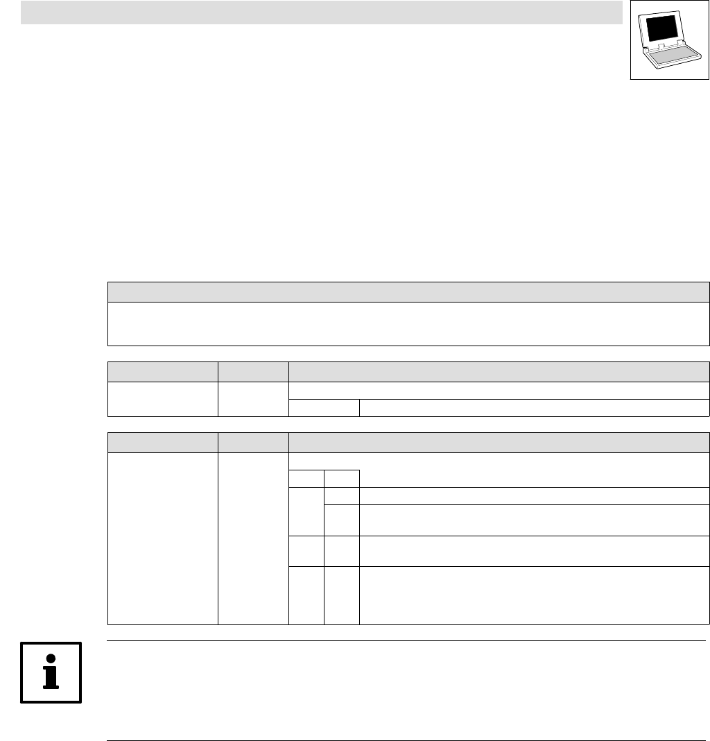
Declaration
DWORD L_CanDSxOpen (bOpen);
Transfer parameters Data type Information/possible settings
bOpen Bool Initialising the CanDSx driver in the operating system.
TRUE The CanDSx driver in the operating system is initialised.
Return value Data type Value/meaning
Double word Status
Bit Value
0 0 Driver is initialised.
1 Driver is not initialised.
· Remedy: function call via transfer parameter bOpen = TRUE.
1−15 Reserved for future supplements (bits are set to 0).
· Invalid for bit 0 = 1
16−31 Version of the LenzeCanDSxDrv.lib
function library
· Format: main version/subversion (e. g. 0103hex = version 1.03)
· Invalid for bit 0 = 1
Note!
If the function L_CanDSxOpenis called up while write or read requests for codes are still active, they
are possibly disturbed!
Therefore all actions with a code access should be completed before this function is called.
Example
Calling the function in ST:
IF bOpenCanDSxDriver AND NOT bOpen THEN
bOpen := TRUE;
dwReturnOpen := L_CanDSxOpen(bOpen:=TRUE);
END_IF