
Instruction Manual
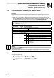
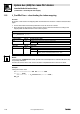
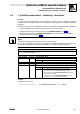
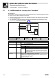
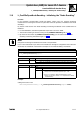

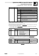
Table Of Contents
- System bus (CAN) for Lenze PLC devices
- This documentation is valid for ...
- Contents
- 1 Preface and general information
- 2 General information on the system bus (CAN)
- 2.1 Introduction
- 2.2 Interfaces of the Lenze PLCs for system bus connection
- 2.3 Identification of the nodes
- 2.4 Structure of the CAN telegram
- 2.5 Network management (NMT)
- 2.6 Transmission of process data
- 2.7 Transmitting parameter data
- 2.8 Free CAN objects
- 2.9 Application recommendations for the different CAN objects
- 2.10 Monitoring mechanisms
- 3 Configuration (system bus - CAN interface)
- 3.1 CAN baud rate
- 3.2 CAN boot-up
- 3.3 Node address (node ID)
- 3.4 Identifiers of the process data objects
- 3.5 Cycle time (CAN2_OUT/CAN3_OUT)
- 3.6 Delay time (CAN2_OUT/CAN3_OUT)
- 3.7 Synchronisation
- 3.8 Reset node
- 3.9 System bus management
- 3.10 Mapping indexes to codes
- 3.11 Remote parameterisation (gateway function)
- 3.12 Monitoring processes
- 3.13 Diagnostics
- 4 Configuration (AIF interface)
- 5 Configuration (FIF interface)
- 6 Configuration (CAN-AUX system bus interface)
- 7 CAN system blocks
- 8 FIF-CAN system blocks (only Drive PLC)
- 9 CAN-AUX system blocks (only ECSxA)
- 10 LenzeCanDrv.lib function library
- 10.1 Overview
- 10.2 Version identifiers of the function library
- 10.3 L_CanInit - initialising the CAN driver
- 10.4 L_CanClose - deactivating the CAN driver
- 10.5 L_CanGetStatus - querying the driver status
- 10.6 L_CanGetRelocCobId - querying the COB-ID range
- 10.7 L_CanPdoTransmit - transmitting a CAN object
- 10.8 L_CanPdoReceive - receiving a CAN object
- 11 LenzeCanDSxDrv.libfunction library
- 11.1 Overview
- 11.2 Version identifiers of the function library
- 11.3 L_CanDSxInitIndexCode - Configuration of index mapping
- 11.4 L_CanDSxOpen - initialising the CanDSx driver
- 11.5 L_CanDSxClose - deactivating the index mapping
- 11.6 L_CanDSxOpenHeartBeat - initialising a "Heartbeat"
- 11.7 L_CanDSxHeartBeat - carrying out a "Heartbeat"
- 11.8 L_CanDSxCloseHeartBeat - deactivating the "Heartbeat"
- 11.9 L_CanDSxOpenNodeGuarding - initialising the "Node Guarding"
- 11.10 L_CanDSxNodeGuarding - carrying out a "Node guarding"
- 11.11 L_CanDSxCloseNodeGuarding - deactivating the "Node Guarding"
- 12 Index
11.10 L_CanDSxNodeGuarding − carrying out a "Node guarding"
System bus (CAN) for Lenze PLC devices
LenzeCanDSxDrv.lib function library
11−12
L
PLC−Systembus EN 2.0
11.10 L_CanDSxNodeGuarding − carrying out a "Node guarding"
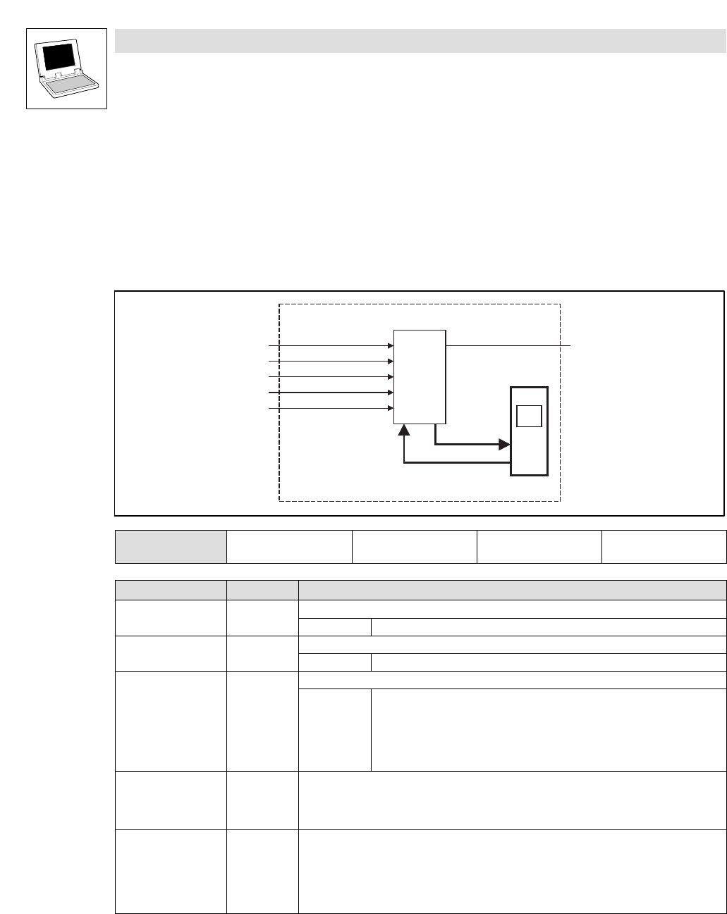
Function block
Use this FB to cyclically monitor the CAN connection between the PLC and other system bus nodes
by means of the so−called "Node guarding" mechanism.
· This monitoring mechanism first has to be initialised in the CanDSx driver using the function
L_CanDSxOpenNodeGuarding.
(^ 11−11)
L_CanDSxNodeGuarding
tNodeGuardTime
wDrvNr
byNodeAddr
bRun
CTRL
nState
NMT Slave
(Node address = )byNodeAddr
System bus
(CAN)
byNodeLifeTimeFactor
1.
2.
FB call in: o Cyclic task
(PLC_PRG)
Þ Time−controlled task
(INTERVAL)
o Event−controlled task
(EVENT)
o Interrupt task
Inputs Data type Information/possible settings
wDrv Word Driver number for the CAN interface of the PLC that is to be used
10 On board system bus (CAN)
byNodeAddr Byte Node address of the node to be monitored.
1...128 Node address
bRun Bool Activating the "Node guarding".
TRUE Monitoring is activated.
· The FB now sends a "remote transmission request" telegram in the
transmission cycle set via tNodeGuardTime to the node with the node address
byNodeAddrand waits for a corresponding response. If it is not effected within
the "NodeLifeTime" monitoring time, the FB outputs a corresponding status at
the output nState.
tNodeGuardTime Time Transmission cycle of the remote transmission request telegram.
· Time interval in which the PLC sends a status request to the node to be monitored (cyclic
polling).
· This setting has to correspond to the "Guard Time" set in the PLC to be monitored (C0382).
byNodeLifeTimeFactor Byte Factor for the so−called "NodeLifeTime".
"NodeLifeTime" = byNodeLifeTimeFactor tNodeGuardTime
· If the node to be monitored does not respond to the status request of the PLC within the
"NodeLifeTime", a "Node Guarding" event is actuated (nState = −10).
· This setting has to correspond to the "NodeLifeTimeFactor" set in the PLC to be monitored
(C0383).