
Instruction Manual
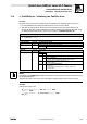
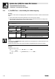
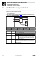
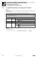
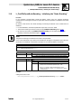

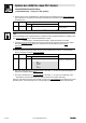
Table Of Contents
- System bus (CAN) for Lenze PLC devices
- This documentation is valid for ...
- Contents
- 1 Preface and general information
- 2 General information on the system bus (CAN)
- 2.1 Introduction
- 2.2 Interfaces of the Lenze PLCs for system bus connection
- 2.3 Identification of the nodes
- 2.4 Structure of the CAN telegram
- 2.5 Network management (NMT)
- 2.6 Transmission of process data
- 2.7 Transmitting parameter data
- 2.8 Free CAN objects
- 2.9 Application recommendations for the different CAN objects
- 2.10 Monitoring mechanisms
- 3 Configuration (system bus - CAN interface)
- 3.1 CAN baud rate
- 3.2 CAN boot-up
- 3.3 Node address (node ID)
- 3.4 Identifiers of the process data objects
- 3.5 Cycle time (CAN2_OUT/CAN3_OUT)
- 3.6 Delay time (CAN2_OUT/CAN3_OUT)
- 3.7 Synchronisation
- 3.8 Reset node
- 3.9 System bus management
- 3.10 Mapping indexes to codes
- 3.11 Remote parameterisation (gateway function)
- 3.12 Monitoring processes
- 3.13 Diagnostics
- 4 Configuration (AIF interface)
- 5 Configuration (FIF interface)
- 6 Configuration (CAN-AUX system bus interface)
- 7 CAN system blocks
- 8 FIF-CAN system blocks (only Drive PLC)
- 9 CAN-AUX system blocks (only ECSxA)
- 10 LenzeCanDrv.lib function library
- 10.1 Overview
- 10.2 Version identifiers of the function library
- 10.3 L_CanInit - initialising the CAN driver
- 10.4 L_CanClose - deactivating the CAN driver
- 10.5 L_CanGetStatus - querying the driver status
- 10.6 L_CanGetRelocCobId - querying the COB-ID range
- 10.7 L_CanPdoTransmit - transmitting a CAN object
- 10.8 L_CanPdoReceive - receiving a CAN object
- 11 LenzeCanDSxDrv.libfunction library
- 11.1 Overview
- 11.2 Version identifiers of the function library
- 11.3 L_CanDSxInitIndexCode - Configuration of index mapping
- 11.4 L_CanDSxOpen - initialising the CanDSx driver
- 11.5 L_CanDSxClose - deactivating the index mapping
- 11.6 L_CanDSxOpenHeartBeat - initialising a "Heartbeat"
- 11.7 L_CanDSxHeartBeat - carrying out a "Heartbeat"
- 11.8 L_CanDSxCloseHeartBeat - deactivating the "Heartbeat"
- 11.9 L_CanDSxOpenNodeGuarding - initialising the "Node Guarding"
- 11.10 L_CanDSxNodeGuarding - carrying out a "Node guarding"
- 11.11 L_CanDSxCloseNodeGuarding - deactivating the "Node Guarding"
- 12 Index
11.10 L_CanDSxNodeGuarding − carrying out a "Node guarding"
System bus (CAN) for Lenze PLC devices
LenzeCanDSxDrv.lib function library
11−14
L
PLC−Systembus EN 2.0
4. Set the factor for the "NodeLifeTime" monitoring time via C0383 in the PLC to be monitored.
This value has to correspond to the setting at the FB input byNodeLifeTimeFactor in the
monitoring PLC:
Code LCD
Possible settings
Information
Lenze Selection
C0383 LifeTimeFact. 0 System bus: Node Guarding (slave):
NodeLifeTimeFactor
0 {1} 255
Tip!
From the settings for the "NodeGuardTime" (C0382) and the "NodeLifeTimeFactor" (C0383) in the
PLC to be monitored, the so−called "NodeLifeTime" results:
NodeLifeTime = NodeGuardTime(C0382)
NodeLifeTimeFactor (C0383)
· If the PLC to be monitored does not receive a status enquiry from the monitoring PLC within
this "NodeLifeTime", a so−called "Life Guarding" event is actuated in the PLC to be
monitored.
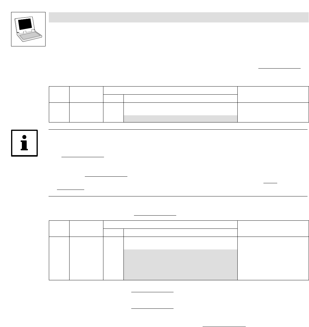
5. Set the desired response by which the PLC to be monitored is to react to a "Life Guarding
Event" via C0384 in the PLC to be monitored
:
Code LCD
Possible settings
Information
Lenze Selection
C0384 Err NodeGuard 3 System bus: Node Guarding (slave):
response to a "Life Guard" event.
0 TRIP
1 Message
2 Warning
3 Off
4 Fail−QSP
6. Set code C0003 in the PLC to be monitored to the value "1" to save the effected changes in a
manner safe against mains failure.
7. Set code C0358 in the PLC to be monitored
to the value "1" to carry out a CAN reset node.
– Alternatively, the CAN reset node can also be carried out by mains switching.
After the CAN reset node has been carried out, the PLC to be monitored
is configured as "node
guarding slave", and monitoring in the "node guarding master" can be activated using this FB.