
Instruction Manual
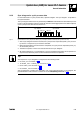
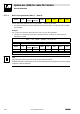
Table Of Contents
- System bus (CAN) for Lenze PLC devices
- This documentation is valid for ...
- Contents
- 1 Preface and general information
- 2 General information on the system bus (CAN)
- 2.1 Introduction
- 2.2 Interfaces of the Lenze PLCs for system bus connection
- 2.3 Identification of the nodes
- 2.4 Structure of the CAN telegram
- 2.5 Network management (NMT)
- 2.6 Transmission of process data
- 2.7 Transmitting parameter data
- 2.8 Free CAN objects
- 2.9 Application recommendations for the different CAN objects
- 2.10 Monitoring mechanisms
- 3 Configuration (system bus - CAN interface)
- 3.1 CAN baud rate
- 3.2 CAN boot-up
- 3.3 Node address (node ID)
- 3.4 Identifiers of the process data objects
- 3.5 Cycle time (CAN2_OUT/CAN3_OUT)
- 3.6 Delay time (CAN2_OUT/CAN3_OUT)
- 3.7 Synchronisation
- 3.8 Reset node
- 3.9 System bus management
- 3.10 Mapping indexes to codes
- 3.11 Remote parameterisation (gateway function)
- 3.12 Monitoring processes
- 3.13 Diagnostics
- 4 Configuration (AIF interface)
- 5 Configuration (FIF interface)
- 6 Configuration (CAN-AUX system bus interface)
- 7 CAN system blocks
- 8 FIF-CAN system blocks (only Drive PLC)
- 9 CAN-AUX system blocks (only ECSxA)
- 10 LenzeCanDrv.lib function library
- 10.1 Overview
- 10.2 Version identifiers of the function library
- 10.3 L_CanInit - initialising the CAN driver
- 10.4 L_CanClose - deactivating the CAN driver
- 10.5 L_CanGetStatus - querying the driver status
- 10.6 L_CanGetRelocCobId - querying the COB-ID range
- 10.7 L_CanPdoTransmit - transmitting a CAN object
- 10.8 L_CanPdoReceive - receiving a CAN object
- 11 LenzeCanDSxDrv.libfunction library
- 11.1 Overview
- 11.2 Version identifiers of the function library
- 11.3 L_CanDSxInitIndexCode - Configuration of index mapping
- 11.4 L_CanDSxOpen - initialising the CanDSx driver
- 11.5 L_CanDSxClose - deactivating the index mapping
- 11.6 L_CanDSxOpenHeartBeat - initialising a "Heartbeat"
- 11.7 L_CanDSxHeartBeat - carrying out a "Heartbeat"
- 11.8 L_CanDSxCloseHeartBeat - deactivating the "Heartbeat"
- 11.9 L_CanDSxOpenNodeGuarding - initialising the "Node Guarding"
- 11.10 L_CanDSxNodeGuarding - carrying out a "Node guarding"
- 11.11 L_CanDSxCloseNodeGuarding - deactivating the "Node Guarding"
- 12 Index
System bus (CAN) for Lenze PLC devices
General information
2−9
l
PLC−Systembus EN 2.0
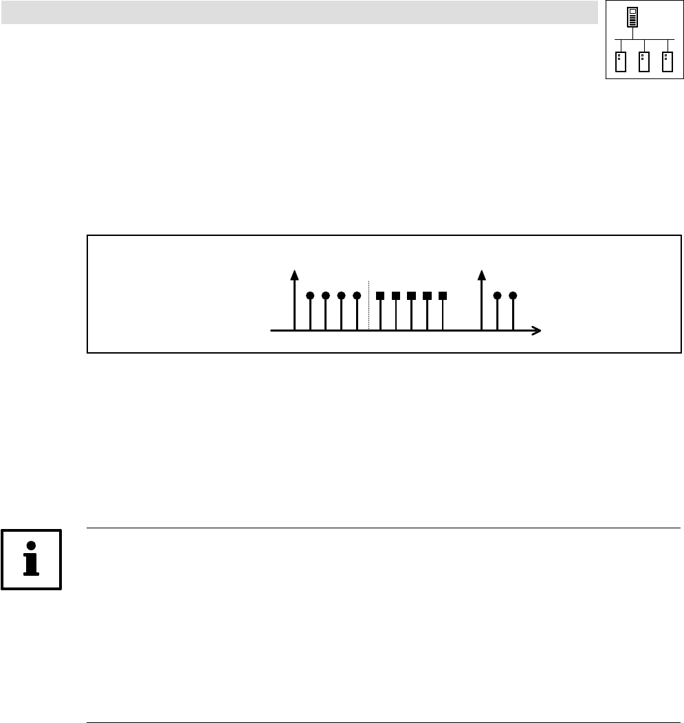
2.6.2 Sync telegram for cyclic process data
For the transmission of cyclic process data, a specific telegram − the sync telegram − is required for
the synchronisation.
The sync telegram which has to be generated by a different node initiates the transmission process
for the cyclic process data of the PLC and at the same time is the trigger point for the data acceptance
of the cyclic process data received in the PLC:
Sync telegram Sync telegram
CAN1_OUT CAN1_IN
1. 2. 3. 4.
Fig. 2−4 Synchronisation of the cyclic process data by a sync telegram (without considering the asynchronous data)
1. After a sync telegram has been received, the cyclic process output data (CAN1_OUT) are sent
by the PLC if "respond to sync" has been activated.
2. When the transmission process has been completed, the cyclic process input data (CAN1_IN)
are received by the PLC.
3. The data acceptance in the PLC is effected with the next sync telegram.
4. All further telegrams (e. g. for parameters or event−controlled process data) are accepted in an
asynchronous manner by the PLC after transmission has been completed.
Tip!
The response to a sync telegram is configured via the following codes:
· for CAN1_OUT via C0366. (^ 3−7)
· for XCAN1_OUT ... XCAN3_OUT via C2375. (^ 4−7)
· for FIF−CAN1_OUT via C2466. (^ 5−7)
· for CANaux1_OUT via C2466. (^ 5−7)
Also the telegrams of CAN2_OUT and CAN3_OUT can be transferred after a sync telegram, the
parameterisation of this function is carried out via the CAN_Management SB.
(^ 7−20)