
Instruction Manual
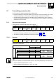
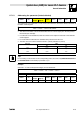
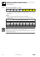
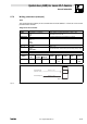
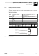
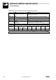
Table Of Contents
- System bus (CAN) for Lenze PLC devices
- This documentation is valid for ...
- Contents
- 1 Preface and general information
- 2 General information on the system bus (CAN)
- 2.1 Introduction
- 2.2 Interfaces of the Lenze PLCs for system bus connection
- 2.3 Identification of the nodes
- 2.4 Structure of the CAN telegram
- 2.5 Network management (NMT)
- 2.6 Transmission of process data
- 2.7 Transmitting parameter data
- 2.8 Free CAN objects
- 2.9 Application recommendations for the different CAN objects
- 2.10 Monitoring mechanisms
- 3 Configuration (system bus - CAN interface)
- 3.1 CAN baud rate
- 3.2 CAN boot-up
- 3.3 Node address (node ID)
- 3.4 Identifiers of the process data objects
- 3.5 Cycle time (CAN2_OUT/CAN3_OUT)
- 3.6 Delay time (CAN2_OUT/CAN3_OUT)
- 3.7 Synchronisation
- 3.8 Reset node
- 3.9 System bus management
- 3.10 Mapping indexes to codes
- 3.11 Remote parameterisation (gateway function)
- 3.12 Monitoring processes
- 3.13 Diagnostics
- 4 Configuration (AIF interface)
- 5 Configuration (FIF interface)
- 6 Configuration (CAN-AUX system bus interface)
- 7 CAN system blocks
- 8 FIF-CAN system blocks (only Drive PLC)
- 9 CAN-AUX system blocks (only ECSxA)
- 10 LenzeCanDrv.lib function library
- 10.1 Overview
- 10.2 Version identifiers of the function library
- 10.3 L_CanInit - initialising the CAN driver
- 10.4 L_CanClose - deactivating the CAN driver
- 10.5 L_CanGetStatus - querying the driver status
- 10.6 L_CanGetRelocCobId - querying the COB-ID range
- 10.7 L_CanPdoTransmit - transmitting a CAN object
- 10.8 L_CanPdoReceive - receiving a CAN object
- 11 LenzeCanDSxDrv.libfunction library
- 11.1 Overview
- 11.2 Version identifiers of the function library
- 11.3 L_CanDSxInitIndexCode - Configuration of index mapping
- 11.4 L_CanDSxOpen - initialising the CanDSx driver
- 11.5 L_CanDSxClose - deactivating the index mapping
- 11.6 L_CanDSxOpenHeartBeat - initialising a "Heartbeat"
- 11.7 L_CanDSxHeartBeat - carrying out a "Heartbeat"
- 11.8 L_CanDSxCloseHeartBeat - deactivating the "Heartbeat"
- 11.9 L_CanDSxOpenNodeGuarding - initialising the "Node Guarding"
- 11.10 L_CanDSxNodeGuarding - carrying out a "Node guarding"
- 11.11 L_CanDSxCloseNodeGuarding - deactivating the "Node Guarding"
- 12 Index

System bus (CAN) for Lenze PLC devices
General information
2−11
l
PLC−Systembus EN 2.0
2.7 Transmitting parameter data
For Lenze devices, parameter data are the so−called codes.
· Parameter settings for instance are carried out in the case of a one−time setting of the system
during commissioning, or in the case of a material change of the production machine.
· Parameter data are transferred as so−called SDOs (Service Data Objects) via the system bus
and are acknowledged by the receiver, i. e. the transmitter receives a feedback on whether the
transmission was successful.
2.7.1 Parameter data telegram
The telegram for parameter data is structured as follows:
11bit 8 bytes user data
Identifier
Command
code
Index
Subindex Data 1 Data 2 Data 3 Data 4
Low byte High byte
· In the following subchapters the different components of the telegram are explained in detail.
· An example for writing a parameter can be found in chapter 2.7.2. (^ 2−15)
· An example for reading a parameter can be found in chapter 2.7.3. (^ 2−17)
2.7.1.1 Identifier
Identifier
Command
code
Index
Subindex Data 1 Data 2 Data 3 Data 4
Low byte High byte
For the transmission of parameter data, two parameter data channels are provided, which are
addressed via the identifier:
Identifier = basic identifier + node address of the node
dec hex
SDOs Parameter data channel 1
Output (transmission) 1536 600
+ C0350
+ C2350
+ C2450
(CAN)
(XCAN)
(FIF−CAN/CANaux)
Input (reception) 1408 580
Parameter data channel 2
Output (transmission) 1600 640
+ C0350
+ C2350
+ C2450
(CAN)
(XCAN)
(FIF−CAN/CANaux)
Input (reception) 1472 5C0
Tip!
Between the identifiers for parameter data channels 1 and 2 there respectively is an offset of 64:
· Output of parameter data channel 1 = 1536
· Output of parameter data channel 2 = 1536 + 64 = 1600