
Instruction Manual
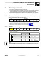
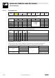
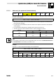
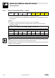
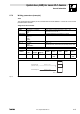
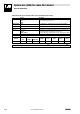
Table Of Contents
- System bus (CAN) for Lenze PLC devices
- This documentation is valid for ...
- Contents
- 1 Preface and general information
- 2 General information on the system bus (CAN)
- 2.1 Introduction
- 2.2 Interfaces of the Lenze PLCs for system bus connection
- 2.3 Identification of the nodes
- 2.4 Structure of the CAN telegram
- 2.5 Network management (NMT)
- 2.6 Transmission of process data
- 2.7 Transmitting parameter data
- 2.8 Free CAN objects
- 2.9 Application recommendations for the different CAN objects
- 2.10 Monitoring mechanisms
- 3 Configuration (system bus - CAN interface)
- 3.1 CAN baud rate
- 3.2 CAN boot-up
- 3.3 Node address (node ID)
- 3.4 Identifiers of the process data objects
- 3.5 Cycle time (CAN2_OUT/CAN3_OUT)
- 3.6 Delay time (CAN2_OUT/CAN3_OUT)
- 3.7 Synchronisation
- 3.8 Reset node
- 3.9 System bus management
- 3.10 Mapping indexes to codes
- 3.11 Remote parameterisation (gateway function)
- 3.12 Monitoring processes
- 3.13 Diagnostics
- 4 Configuration (AIF interface)
- 5 Configuration (FIF interface)
- 6 Configuration (CAN-AUX system bus interface)
- 7 CAN system blocks
- 8 FIF-CAN system blocks (only Drive PLC)
- 9 CAN-AUX system blocks (only ECSxA)
- 10 LenzeCanDrv.lib function library
- 10.1 Overview
- 10.2 Version identifiers of the function library
- 10.3 L_CanInit - initialising the CAN driver
- 10.4 L_CanClose - deactivating the CAN driver
- 10.5 L_CanGetStatus - querying the driver status
- 10.6 L_CanGetRelocCobId - querying the COB-ID range
- 10.7 L_CanPdoTransmit - transmitting a CAN object
- 10.8 L_CanPdoReceive - receiving a CAN object
- 11 LenzeCanDSxDrv.libfunction library
- 11.1 Overview
- 11.2 Version identifiers of the function library
- 11.3 L_CanDSxInitIndexCode - Configuration of index mapping
- 11.4 L_CanDSxOpen - initialising the CanDSx driver
- 11.5 L_CanDSxClose - deactivating the index mapping
- 11.6 L_CanDSxOpenHeartBeat - initialising a "Heartbeat"
- 11.7 L_CanDSxHeartBeat - carrying out a "Heartbeat"
- 11.8 L_CanDSxCloseHeartBeat - deactivating the "Heartbeat"
- 11.9 L_CanDSxOpenNodeGuarding - initialising the "Node Guarding"
- 11.10 L_CanDSxNodeGuarding - carrying out a "Node guarding"
- 11.11 L_CanDSxCloseNodeGuarding - deactivating the "Node Guarding"
- 12 Index
System bus (CAN) for Lenze PLC devices
General information
2−15
l
PLC−Systembus EN 2.0
2.7.2 Writing parameters (example)
Task
The acceleration time (C0012) of the controller with the node address 1 is to be set to 20 s via the
parameter data channel 1.
Telegram to the controller
Formula Information
Identifier = basic identifier + node address
= 1536 + 1
= 1537
· Basic identifier for parameter data channel 1 (output) = 1536
· Node address of the controller = 1
Command code = 23
hex
· Command "Write Request" (send parameter to controller)
Index = 24575 − number of the Lenze code
= 24575 − 12
= 24563
= 5F F3
hex
· Code = C0012 (acceleration time)
Subindex = 0 · Subcode = 0 (no subcode)
Data 1 ... 4 = 20 x 10000
= 200000
= 00 03 0D 40
hex
· Value = 20 s
· Fixed32 data format (4 fixed decimal positions); multiply value by 10000
11bit 8 bytes user data
Identifier
Command
code
Index
Subindex Data 1 Data 2 Data 3 Data 4
Low byte High byte
1537 23
hex
F3
hex
5F
hex
0 40
hex
0D
hex
03
hex
00
hex
(LSB) (MSB)
Identifier = 1537
L
SDO 1 / Node-ID 1
Identifier = 1409
Write Request
(C0012 = 20 s)
Write Response
Fig. 2−5 Writing parameters