
Instruction Manual
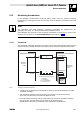

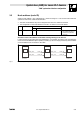
Table Of Contents
- System bus (CAN) for Lenze PLC devices
- This documentation is valid for ...
- Contents
- 1 Preface and general information
- 2 General information on the system bus (CAN)
- 2.1 Introduction
- 2.2 Interfaces of the Lenze PLCs for system bus connection
- 2.3 Identification of the nodes
- 2.4 Structure of the CAN telegram
- 2.5 Network management (NMT)
- 2.6 Transmission of process data
- 2.7 Transmitting parameter data
- 2.8 Free CAN objects
- 2.9 Application recommendations for the different CAN objects
- 2.10 Monitoring mechanisms
- 3 Configuration (system bus - CAN interface)
- 3.1 CAN baud rate
- 3.2 CAN boot-up
- 3.3 Node address (node ID)
- 3.4 Identifiers of the process data objects
- 3.5 Cycle time (CAN2_OUT/CAN3_OUT)
- 3.6 Delay time (CAN2_OUT/CAN3_OUT)
- 3.7 Synchronisation
- 3.8 Reset node
- 3.9 System bus management
- 3.10 Mapping indexes to codes
- 3.11 Remote parameterisation (gateway function)
- 3.12 Monitoring processes
- 3.13 Diagnostics
- 4 Configuration (AIF interface)
- 5 Configuration (FIF interface)
- 6 Configuration (CAN-AUX system bus interface)
- 7 CAN system blocks
- 8 FIF-CAN system blocks (only Drive PLC)
- 9 CAN-AUX system blocks (only ECSxA)
- 10 LenzeCanDrv.lib function library
- 10.1 Overview
- 10.2 Version identifiers of the function library
- 10.3 L_CanInit - initialising the CAN driver
- 10.4 L_CanClose - deactivating the CAN driver
- 10.5 L_CanGetStatus - querying the driver status
- 10.6 L_CanGetRelocCobId - querying the COB-ID range
- 10.7 L_CanPdoTransmit - transmitting a CAN object
- 10.8 L_CanPdoReceive - receiving a CAN object
- 11 LenzeCanDSxDrv.libfunction library
- 11.1 Overview
- 11.2 Version identifiers of the function library
- 11.3 L_CanDSxInitIndexCode - Configuration of index mapping
- 11.4 L_CanDSxOpen - initialising the CanDSx driver
- 11.5 L_CanDSxClose - deactivating the index mapping
- 11.6 L_CanDSxOpenHeartBeat - initialising a "Heartbeat"
- 11.7 L_CanDSxHeartBeat - carrying out a "Heartbeat"
- 11.8 L_CanDSxCloseHeartBeat - deactivating the "Heartbeat"
- 11.9 L_CanDSxOpenNodeGuarding - initialising the "Node Guarding"
- 11.10 L_CanDSxNodeGuarding - carrying out a "Node guarding"
- 11.11 L_CanDSxCloseNodeGuarding - deactivating the "Node Guarding"
- 12 Index
System bus (CAN) for Lenze PLC devices
General information
2−21
l
PLC−Systembus EN 2.0
2.10 Monitoring mechanisms
In the CANopen communication profile (CiA DS301, version 4.01) two optional monitoring
mechanisms for ensuring the function of system bus nodes are specified, "Heartbeat" and "Node
Guarding".
Note!
The "Heartbeat" and "Node Guarding" monitoring mechanisms are supported by the
9300 Servo PLC, Drive, PLC and by the ECSxA axis module as of V6.0.
The initialisation and execution of the monitoring mechanisms is carried out by means of the
functions/function blocks of the LenzeCanDSxDrv.lib function library.
(^ 11−1)
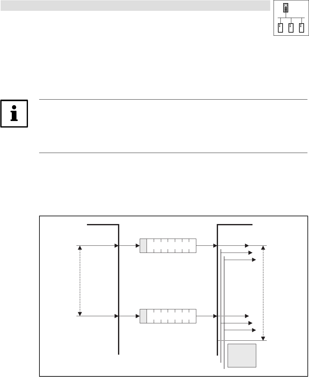
2.10.1 "Heartbeat"
The "Heartbeat" monitoring mechanism is a Producer−Consumer−oriented method which does not
require an enquiry message and where each node is able to monitor the state of all other nodes.
Request
Request
Indication(s)
Heartbeat
Producer
Time
Heartbeat Producer Heartbeat Consumer(s)
r
s
Heartbeat
Event
Heartbeat
Consumer
Time
18
r
s
18
Indication(s)
r:
Stopped
Operational
Pre-Operational
Boot-Up Event
reserved
s: State of the heartbeat producer:
4
5
127
0
Fig. 2−7 "Heartbeat" monitoring mechanism
· A node (Producer) signalises its communication status by cyclically transmitting a so−called
"Heartbeat" message.
· This "Heartbeat" message can be received by one, several, or by all the other nodes
(Consumer), and thus they can monitor the respective node.
· If the responsible, monitoring node (Consumer) does not receive the "Heartbeat" message
from the node to be monitored (Producer) within the set monitoring time
(HeartBeatConsumerTime), a "Heartbeat" event is displayed in its application.