
Instruction Manual
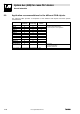
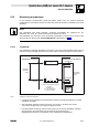
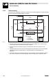

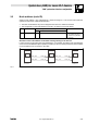
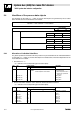
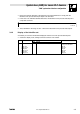
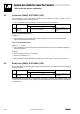
Table Of Contents
- System bus (CAN) for Lenze PLC devices
- This documentation is valid for ...
- Contents
- 1 Preface and general information
- 2 General information on the system bus (CAN)
- 2.1 Introduction
- 2.2 Interfaces of the Lenze PLCs for system bus connection
- 2.3 Identification of the nodes
- 2.4 Structure of the CAN telegram
- 2.5 Network management (NMT)
- 2.6 Transmission of process data
- 2.7 Transmitting parameter data
- 2.8 Free CAN objects
- 2.9 Application recommendations for the different CAN objects
- 2.10 Monitoring mechanisms
- 3 Configuration (system bus - CAN interface)
- 3.1 CAN baud rate
- 3.2 CAN boot-up
- 3.3 Node address (node ID)
- 3.4 Identifiers of the process data objects
- 3.5 Cycle time (CAN2_OUT/CAN3_OUT)
- 3.6 Delay time (CAN2_OUT/CAN3_OUT)
- 3.7 Synchronisation
- 3.8 Reset node
- 3.9 System bus management
- 3.10 Mapping indexes to codes
- 3.11 Remote parameterisation (gateway function)
- 3.12 Monitoring processes
- 3.13 Diagnostics
- 4 Configuration (AIF interface)
- 5 Configuration (FIF interface)
- 6 Configuration (CAN-AUX system bus interface)
- 7 CAN system blocks
- 8 FIF-CAN system blocks (only Drive PLC)
- 9 CAN-AUX system blocks (only ECSxA)
- 10 LenzeCanDrv.lib function library
- 10.1 Overview
- 10.2 Version identifiers of the function library
- 10.3 L_CanInit - initialising the CAN driver
- 10.4 L_CanClose - deactivating the CAN driver
- 10.5 L_CanGetStatus - querying the driver status
- 10.6 L_CanGetRelocCobId - querying the COB-ID range
- 10.7 L_CanPdoTransmit - transmitting a CAN object
- 10.8 L_CanPdoReceive - receiving a CAN object
- 11 LenzeCanDSxDrv.libfunction library
- 11.1 Overview
- 11.2 Version identifiers of the function library
- 11.3 L_CanDSxInitIndexCode - Configuration of index mapping
- 11.4 L_CanDSxOpen - initialising the CanDSx driver
- 11.5 L_CanDSxClose - deactivating the index mapping
- 11.6 L_CanDSxOpenHeartBeat - initialising a "Heartbeat"
- 11.7 L_CanDSxHeartBeat - carrying out a "Heartbeat"
- 11.8 L_CanDSxCloseHeartBeat - deactivating the "Heartbeat"
- 11.9 L_CanDSxOpenNodeGuarding - initialising the "Node Guarding"
- 11.10 L_CanDSxNodeGuarding - carrying out a "Node guarding"
- 11.11 L_CanDSxCloseNodeGuarding - deactivating the "Node Guarding"
- 12 Index
System bus (CAN) for Lenze PLC devices
"CAN" system bus interface configuration
3−4
l
PLC−Systembus EN 2.0
3.4 Identifiers of the process data objects
The identifiers for the CAN1_IO ... CAN3_IO process data objects are generated by the so−called
basic identifier and the node address set in C0350:
Identifier + basic identifier ) node address
Basic identifiers
dec hex
PDOs CAN1_IO (cyclic process data)
CAN1_IN 512 200
CAN1_OUT 384 180
CAN2_IO (event− or time−controlled process data)
CAN2_IN 640 280
CAN2_OUT 641 281
CAN3_IO (event− or time−controlled process data)
CAN3_IN 768 300
CAN3_OUT 769 301
3.4.1 Allocation of individual identifiers
For greater system bus networks with many nodes it may be reasonable to set individual identifiers
for the CAN1_IO ... CAN3_IO process data objects via C0353/C0354, which are independent of the
node address set in C0350:
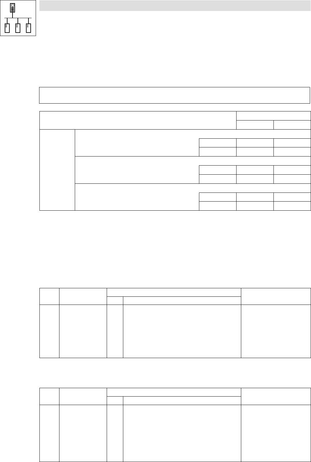
1. Set C0353/x to "1".
– (x = subcode of the corresponding process data object):
Code LCD
Possible settings
Information
Lenze Selection
C0353 CAN addr sel 0 Identifier assignment under C0350 + basic
identifier
1 Identifier assignment under C0354/x
Source for the identifiers of the
process data objects
· Save changes with C0003 = 1.
· Changes are only valid after
reset node!
1 CAN addr sel1 0 CAN1_IN/OUT
2 CAN addr sel2 0 CAN2_IN/OUT
3 CAN addr sel3 0 CAN3_IN/OUT
2. Set the value which added to "384" makes the desired identifier in C0354/x.
– (x = subcode of the corresponding process data object):
Code LCD
Possible settings
Information
Lenze Selection
C0354 CAN addr 1 {1} 512 Specification of individual
identifiers for the process data
objects
1
2
3
4
5
6
IN1 addr2
OUT1 addr2
IN2 addr2
OUT2 addr2
IN3 addr2
OUT3 addr2
129
1
257
258
385
386
CAN1_IN
CAN1_OUT
CAN2_IN
CAN2_OUT
CAN3_IN
CAN3_OUT