
Instruction Manual
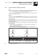
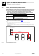
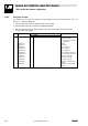
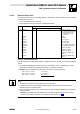
Table Of Contents
- System bus (CAN) for Lenze PLC devices
- This documentation is valid for ...
- Contents
- 1 Preface and general information
- 2 General information on the system bus (CAN)
- 2.1 Introduction
- 2.2 Interfaces of the Lenze PLCs for system bus connection
- 2.3 Identification of the nodes
- 2.4 Structure of the CAN telegram
- 2.5 Network management (NMT)
- 2.6 Transmission of process data
- 2.7 Transmitting parameter data
- 2.8 Free CAN objects
- 2.9 Application recommendations for the different CAN objects
- 2.10 Monitoring mechanisms
- 3 Configuration (system bus - CAN interface)
- 3.1 CAN baud rate
- 3.2 CAN boot-up
- 3.3 Node address (node ID)
- 3.4 Identifiers of the process data objects
- 3.5 Cycle time (CAN2_OUT/CAN3_OUT)
- 3.6 Delay time (CAN2_OUT/CAN3_OUT)
- 3.7 Synchronisation
- 3.8 Reset node
- 3.9 System bus management
- 3.10 Mapping indexes to codes
- 3.11 Remote parameterisation (gateway function)
- 3.12 Monitoring processes
- 3.13 Diagnostics
- 4 Configuration (AIF interface)
- 5 Configuration (FIF interface)
- 6 Configuration (CAN-AUX system bus interface)
- 7 CAN system blocks
- 8 FIF-CAN system blocks (only Drive PLC)
- 9 CAN-AUX system blocks (only ECSxA)
- 10 LenzeCanDrv.lib function library
- 10.1 Overview
- 10.2 Version identifiers of the function library
- 10.3 L_CanInit - initialising the CAN driver
- 10.4 L_CanClose - deactivating the CAN driver
- 10.5 L_CanGetStatus - querying the driver status
- 10.6 L_CanGetRelocCobId - querying the COB-ID range
- 10.7 L_CanPdoTransmit - transmitting a CAN object
- 10.8 L_CanPdoReceive - receiving a CAN object
- 11 LenzeCanDSxDrv.libfunction library
- 11.1 Overview
- 11.2 Version identifiers of the function library
- 11.3 L_CanDSxInitIndexCode - Configuration of index mapping
- 11.4 L_CanDSxOpen - initialising the CanDSx driver
- 11.5 L_CanDSxClose - deactivating the index mapping
- 11.6 L_CanDSxOpenHeartBeat - initialising a "Heartbeat"
- 11.7 L_CanDSxHeartBeat - carrying out a "Heartbeat"
- 11.8 L_CanDSxCloseHeartBeat - deactivating the "Heartbeat"
- 11.9 L_CanDSxOpenNodeGuarding - initialising the "Node Guarding"
- 11.10 L_CanDSxNodeGuarding - carrying out a "Node guarding"
- 11.11 L_CanDSxCloseNodeGuarding - deactivating the "Node Guarding"
- 12 Index
System bus (CAN) for Lenze PLC devices
"CAN" system bus interface configuration
3−9
l
PLC−Systembus EN 2.0
3.10.1 Functional principle considering as example
Task
Within the PLC, a function has been realised from the user side, which can be parameterised via the
user code C3200/5. The index 21375
dec
is automatically assigned to code C3200:
Index = 24575
dec
− code = 24575
dec
− 3200 = 21375
dec
On the basis of the communication profile used, this function, however, is to be parameterisable via
the index 4101
dec
/subindex 2 instead.
Solution
Via the functions of the LenzeCanDSxDrv.lib function library, index 4101
dec
/subindex 2 is simply
diverted to code C3200/5 within the PLC, so that the communication profile can be used unchanged.
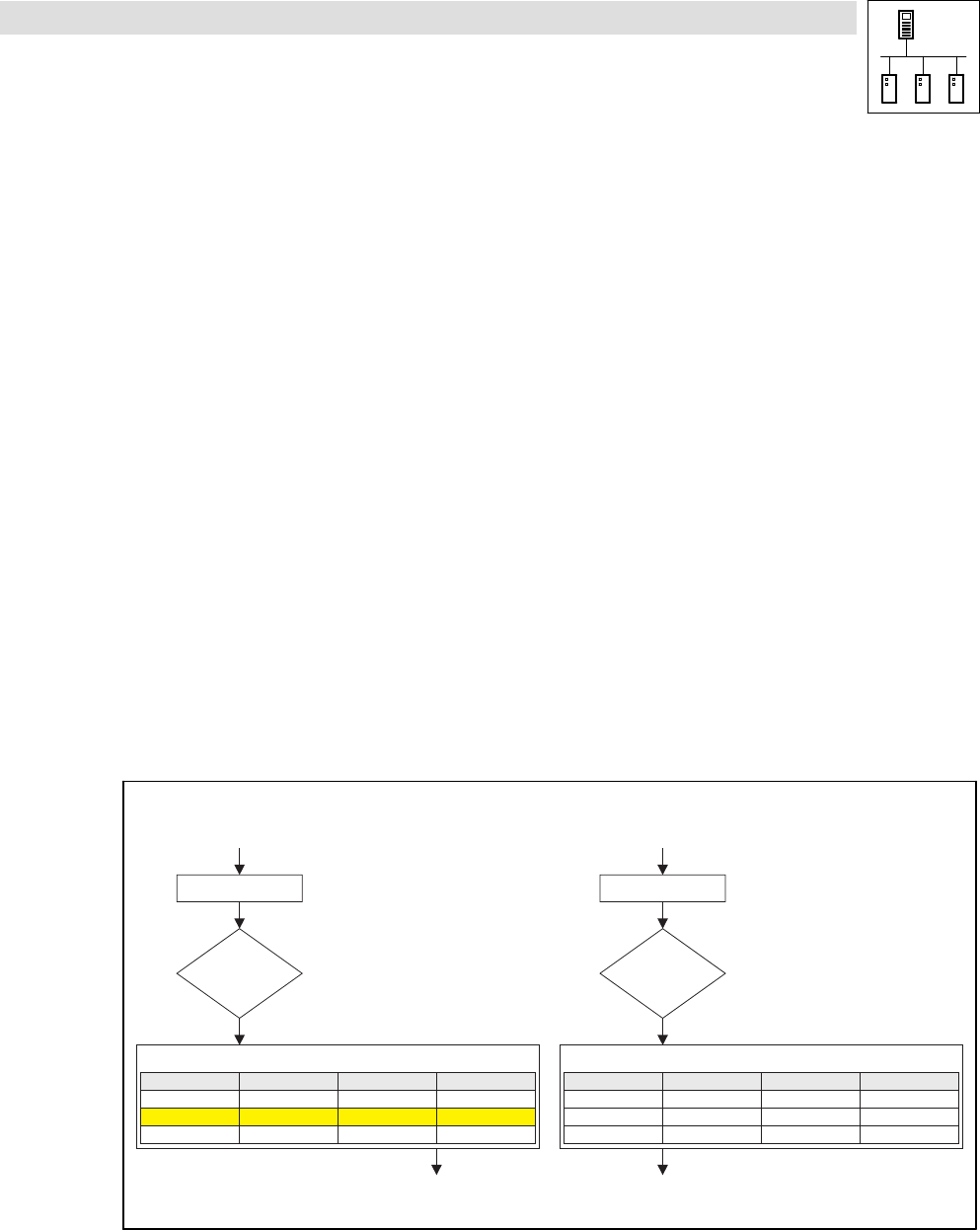
Functional principle
The operating system (as of V6.0) of the Lenze PLCs contains a so−called "mapping table". With this
table up to 256 indexes within the PLC can be "mapped" to other codes than to those which are
automatically allocated.
If a CAN telegram arrives and the index is in the valid range, it is checked whether this index is listed
in the mapping table.
· If the index is listed in the mapping table, the code which has been newly assigned to this
index in the mapping table is accessed.
·
If the index is not listed in the mapping table, the code which is automatically allocated is
accessed, resulting from the above−mentioned formula.
SDO telegram
Index number
valid ?
CAN subindex
4101
yes
Index access: 4101/2
Code access: C3200/5
Mapping table
CAN index Lenze code Lenze subcode
2 3200 5
4101
1
20000 0
3200
4
3000
0
SDO telegram
Index number
valid ?
CAN subindex
4101
yes
Index access: 21475/1
Lenze code = 24575 - Index = 24575 - 21475 = 3100
Code access = C3100/1
Mapping table
CAN index Lenze code Lenze subcode
2 3200 5
4101
1
20000 0
3200
4
3000
0
Fig. 3−2 Process of diverting indexes to codes