
Instruction Manual
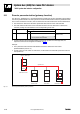
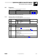
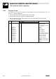
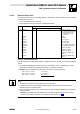
Table Of Contents
- System bus (CAN) for Lenze PLC devices
- This documentation is valid for ...
- Contents
- 1 Preface and general information
- 2 General information on the system bus (CAN)
- 2.1 Introduction
- 2.2 Interfaces of the Lenze PLCs for system bus connection
- 2.3 Identification of the nodes
- 2.4 Structure of the CAN telegram
- 2.5 Network management (NMT)
- 2.6 Transmission of process data
- 2.7 Transmitting parameter data
- 2.8 Free CAN objects
- 2.9 Application recommendations for the different CAN objects
- 2.10 Monitoring mechanisms
- 3 Configuration (system bus - CAN interface)
- 3.1 CAN baud rate
- 3.2 CAN boot-up
- 3.3 Node address (node ID)
- 3.4 Identifiers of the process data objects
- 3.5 Cycle time (CAN2_OUT/CAN3_OUT)
- 3.6 Delay time (CAN2_OUT/CAN3_OUT)
- 3.7 Synchronisation
- 3.8 Reset node
- 3.9 System bus management
- 3.10 Mapping indexes to codes
- 3.11 Remote parameterisation (gateway function)
- 3.12 Monitoring processes
- 3.13 Diagnostics
- 4 Configuration (AIF interface)
- 5 Configuration (FIF interface)
- 6 Configuration (CAN-AUX system bus interface)
- 7 CAN system blocks
- 8 FIF-CAN system blocks (only Drive PLC)
- 9 CAN-AUX system blocks (only ECSxA)
- 10 LenzeCanDrv.lib function library
- 10.1 Overview
- 10.2 Version identifiers of the function library
- 10.3 L_CanInit - initialising the CAN driver
- 10.4 L_CanClose - deactivating the CAN driver
- 10.5 L_CanGetStatus - querying the driver status
- 10.6 L_CanGetRelocCobId - querying the COB-ID range
- 10.7 L_CanPdoTransmit - transmitting a CAN object
- 10.8 L_CanPdoReceive - receiving a CAN object
- 11 LenzeCanDSxDrv.libfunction library
- 11.1 Overview
- 11.2 Version identifiers of the function library
- 11.3 L_CanDSxInitIndexCode - Configuration of index mapping
- 11.4 L_CanDSxOpen - initialising the CanDSx driver
- 11.5 L_CanDSxClose - deactivating the index mapping
- 11.6 L_CanDSxOpenHeartBeat - initialising a "Heartbeat"
- 11.7 L_CanDSxHeartBeat - carrying out a "Heartbeat"
- 11.8 L_CanDSxCloseHeartBeat - deactivating the "Heartbeat"
- 11.9 L_CanDSxOpenNodeGuarding - initialising the "Node Guarding"
- 11.10 L_CanDSxNodeGuarding - carrying out a "Node guarding"
- 11.11 L_CanDSxCloseNodeGuarding - deactivating the "Node Guarding"
- 12 Index
System bus (CAN) for Lenze PLC devices
"CAN" system bus interface configuration
3−10
l
PLC−Systembus EN 2.0
3.11 Remote parameterisation (gateway function)
The drive PLC, 9300 Servo PLC, and the ECSxA axis module as of the V6.x operating system support
the remote parameterisation of other system bus nodes. All write/read accesses to parameters then
are no more carried out in the PLC, but are diverted to the node selected for remote maintenance.
· The diversion is effected via the SDO1 parameter data channel of the node selected.
· The node which the diversion of the write/read accesses is to be effected to is defined via
C0370 by setting the node address of the corresponding node here:
Code LCD
Possible settings
Information
Lenze Selection
C0370 Gateway addr. 0 System bus: Activate remote
parameter setting
0 {1} 63
0 = remote parameter setting deactivated
· A timeout during remote parameterisation actuates the system error message CE5; the
response to this can be configured via C0603.
(^ 3−12)
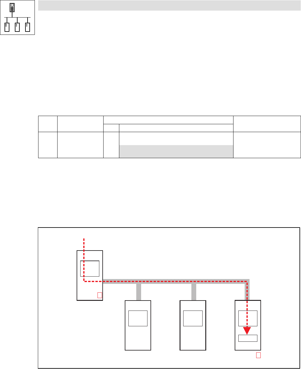
Example
· The system bus node with the node address 5 has been selected for the remote
parameterisation (C0370 = 5).
· A write access to code C0011 is carried out, it is diverted to the selected system bus node via
the system bus:
L
Node-ID 1
"9300 Servo PLC"
Node-ID 3
"8200 vector"
Node-ID 9
"Drive PLC"
L
Node-ID 5
"9300 Servo PLC"
L L
C0370 = 5
C0011
C0011 = 3005 rpm
System bus
Fig. 3−3 Remote parameterisation (gateway function)