
Instruction Manual
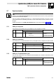
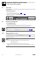
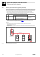
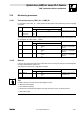
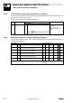
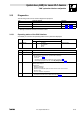
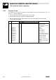
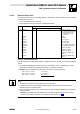
Table Of Contents
- System bus (CAN) for Lenze PLC devices
- This documentation is valid for ...
- Contents
- 1 Preface and general information
- 2 General information on the system bus (CAN)
- 2.1 Introduction
- 2.2 Interfaces of the Lenze PLCs for system bus connection
- 2.3 Identification of the nodes
- 2.4 Structure of the CAN telegram
- 2.5 Network management (NMT)
- 2.6 Transmission of process data
- 2.7 Transmitting parameter data
- 2.8 Free CAN objects
- 2.9 Application recommendations for the different CAN objects
- 2.10 Monitoring mechanisms
- 3 Configuration (system bus - CAN interface)
- 3.1 CAN baud rate
- 3.2 CAN boot-up
- 3.3 Node address (node ID)
- 3.4 Identifiers of the process data objects
- 3.5 Cycle time (CAN2_OUT/CAN3_OUT)
- 3.6 Delay time (CAN2_OUT/CAN3_OUT)
- 3.7 Synchronisation
- 3.8 Reset node
- 3.9 System bus management
- 3.10 Mapping indexes to codes
- 3.11 Remote parameterisation (gateway function)
- 3.12 Monitoring processes
- 3.13 Diagnostics
- 4 Configuration (AIF interface)
- 5 Configuration (FIF interface)
- 6 Configuration (CAN-AUX system bus interface)
- 7 CAN system blocks
- 8 FIF-CAN system blocks (only Drive PLC)
- 9 CAN-AUX system blocks (only ECSxA)
- 10 LenzeCanDrv.lib function library
- 10.1 Overview
- 10.2 Version identifiers of the function library
- 10.3 L_CanInit - initialising the CAN driver
- 10.4 L_CanClose - deactivating the CAN driver
- 10.5 L_CanGetStatus - querying the driver status
- 10.6 L_CanGetRelocCobId - querying the COB-ID range
- 10.7 L_CanPdoTransmit - transmitting a CAN object
- 10.8 L_CanPdoReceive - receiving a CAN object
- 11 LenzeCanDSxDrv.libfunction library
- 11.1 Overview
- 11.2 Version identifiers of the function library
- 11.3 L_CanDSxInitIndexCode - Configuration of index mapping
- 11.4 L_CanDSxOpen - initialising the CanDSx driver
- 11.5 L_CanDSxClose - deactivating the index mapping
- 11.6 L_CanDSxOpenHeartBeat - initialising a "Heartbeat"
- 11.7 L_CanDSxHeartBeat - carrying out a "Heartbeat"
- 11.8 L_CanDSxCloseHeartBeat - deactivating the "Heartbeat"
- 11.9 L_CanDSxOpenNodeGuarding - initialising the "Node Guarding"
- 11.10 L_CanDSxNodeGuarding - carrying out a "Node guarding"
- 11.11 L_CanDSxCloseNodeGuarding - deactivating the "Node Guarding"
- 12 Index
System bus (CAN) for Lenze PLC devices
"CAN" system bus interface configuration
3−12
l
PLC−Systembus EN 2.0
3.12.3 Time−out when remote parameterisation is activated
If a time−out occurs during the remote parameterisation (gateway function) activated via C0370, the
system error message CE5 is output.
The response to this can be configured via C0603:
Code LCD
Possible settings
Information
Lenze Selection
C0603 MONIT CE5 3 System bus: Monitoring
configuration
Time−out when remote
parameterisation is activated
(C0370)
0 TRIP
2 Warning
3 Off
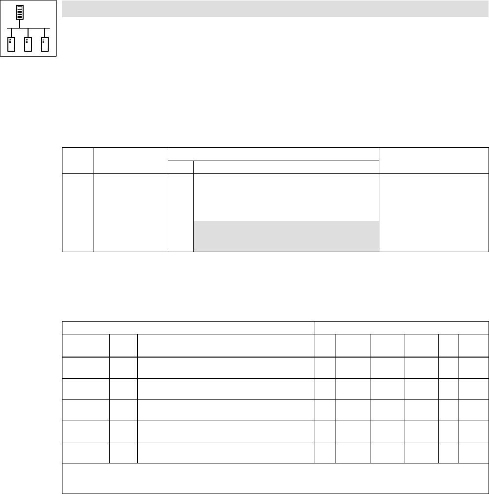
3.12.4 Response in the case of system bus fault messages
Overview of the system bus error sources registered by the PLC and of the possible settings for the
corresponding response:
Fault message Possible settings/response
Display Error
No.
Meaning TRIP Message Warning Fault/QS
P
Off Code
CE1 62 CAN1_IN communication error
(time monitoring can be set via C0357/1)
ü − ü − • C0591
CE2 63 CAN2_IN communication error
(time monitoring can be set via C0357/2)
ü − ü − • C0592
CE3 64 CAN3_IN communication error
(time monitoring can be set via C0357/3)
ü − ü − • C0593
CE4 65 BUS−OFF state
(too many faulty telegrams were received)
ü − ü − • C0595
CE5 66 CAN time−out
(gateway function C0370)
ü − ü − • C0603
• Lenze setting
ü Possible
− Not possible