
Instruction Manual
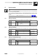
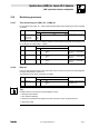
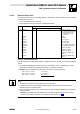
Table Of Contents
- System bus (CAN) for Lenze PLC devices
- This documentation is valid for ...
- Contents
- 1 Preface and general information
- 2 General information on the system bus (CAN)
- 2.1 Introduction
- 2.2 Interfaces of the Lenze PLCs for system bus connection
- 2.3 Identification of the nodes
- 2.4 Structure of the CAN telegram
- 2.5 Network management (NMT)
- 2.6 Transmission of process data
- 2.7 Transmitting parameter data
- 2.8 Free CAN objects
- 2.9 Application recommendations for the different CAN objects
- 2.10 Monitoring mechanisms
- 3 Configuration (system bus - CAN interface)
- 3.1 CAN baud rate
- 3.2 CAN boot-up
- 3.3 Node address (node ID)
- 3.4 Identifiers of the process data objects
- 3.5 Cycle time (CAN2_OUT/CAN3_OUT)
- 3.6 Delay time (CAN2_OUT/CAN3_OUT)
- 3.7 Synchronisation
- 3.8 Reset node
- 3.9 System bus management
- 3.10 Mapping indexes to codes
- 3.11 Remote parameterisation (gateway function)
- 3.12 Monitoring processes
- 3.13 Diagnostics
- 4 Configuration (AIF interface)
- 5 Configuration (FIF interface)
- 6 Configuration (CAN-AUX system bus interface)
- 7 CAN system blocks
- 8 FIF-CAN system blocks (only Drive PLC)
- 9 CAN-AUX system blocks (only ECSxA)
- 10 LenzeCanDrv.lib function library
- 10.1 Overview
- 10.2 Version identifiers of the function library
- 10.3 L_CanInit - initialising the CAN driver
- 10.4 L_CanClose - deactivating the CAN driver
- 10.5 L_CanGetStatus - querying the driver status
- 10.6 L_CanGetRelocCobId - querying the COB-ID range
- 10.7 L_CanPdoTransmit - transmitting a CAN object
- 10.8 L_CanPdoReceive - receiving a CAN object
- 11 LenzeCanDSxDrv.libfunction library
- 11.1 Overview
- 11.2 Version identifiers of the function library
- 11.3 L_CanDSxInitIndexCode - Configuration of index mapping
- 11.4 L_CanDSxOpen - initialising the CanDSx driver
- 11.5 L_CanDSxClose - deactivating the index mapping
- 11.6 L_CanDSxOpenHeartBeat - initialising a "Heartbeat"
- 11.7 L_CanDSxHeartBeat - carrying out a "Heartbeat"
- 11.8 L_CanDSxCloseHeartBeat - deactivating the "Heartbeat"
- 11.9 L_CanDSxOpenNodeGuarding - initialising the "Node Guarding"
- 11.10 L_CanDSxNodeGuarding - carrying out a "Node guarding"
- 11.11 L_CanDSxCloseNodeGuarding - deactivating the "Node Guarding"
- 12 Index
System bus (CAN) for Lenze PLC devices
"CAN" system bus interface configuration
3−15
l
PLC−Systembus EN 2.0
3.13.3 Bus load by the PLC
Via C0361 you can receive a percentage display of the extent to which the system bus is loaded by
the telegrams of the PLC.
· Only valid telegrams are considered.
· Each transmit and receive channel is evaluated separately.
Code LCD
Possible settings
Information
Lenze Selection
C0361 Load IN/OUT
g
0 {1 %} 100 System bus − bus load
· Trouble−free operation demands
that the total bus load (all
connected devices) does not
exceed 80 %.
1 Load OUT All sent
2 Load IN All received
3 Load OUT1 Sent on CAN_OUT1
4 Load OUT2 Sent on CAN_OUT2
5 Load OUT3 Sent on CAN_OUT3
6 Load POUT1 Sent on parameter data channel 1
7 Load POUT2 Sent on parameter data channel 2
8 Load IN1 Received from CAN_IN1
9 Load IN2 Received from CAN_IN2
10 Load IN3 Received from CAN_IN3
11 Load PIN1 Received from parameter data
channel 1
12 Load PIN2 Received from parameter data
channel 2
Limits of the data transmission
Data transmission is limited by the number of telegrams per time unit and by the data transmission
speed.
· For a data exchange within a drive system only consisting of Lenze controllers/PLCs, these
limits can be determined by adding code C0361/1 of all devices involved.
· Example: Three controllers are connected to each other via the system bus:
Value of C0361/1 on controller 1: 23.5 % bus load
Value of C0361/1 on controller 2: 12.6 % bus load
Value of C0361/1 on controller 3: 16.0 % bus load
52.1 % total bus load
Tip!
· The bus load of all devices involved should not exceed 80 %.
· If other devices, like for example decentralised inputs and outputs are connected, these
telegrams are to be considered also.
· A bus overload for instance can be effected by an event−controlled transmission of continually
changing signals.
– Remedy: Accordingly alter the setting of the cycle time for CAN2_OUT or CAN3_OUT, so
that the total of all bus loads does not exceed the value of 80 %.
(^ 3−6)