
Instruction Manual
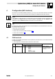
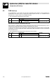
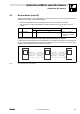
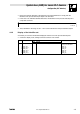
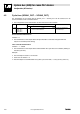
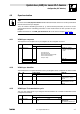
Table Of Contents
- System bus (CAN) for Lenze PLC devices
- This documentation is valid for ...
- Contents
- 1 Preface and general information
- 2 General information on the system bus (CAN)
- 2.1 Introduction
- 2.2 Interfaces of the Lenze PLCs for system bus connection
- 2.3 Identification of the nodes
- 2.4 Structure of the CAN telegram
- 2.5 Network management (NMT)
- 2.6 Transmission of process data
- 2.7 Transmitting parameter data
- 2.8 Free CAN objects
- 2.9 Application recommendations for the different CAN objects
- 2.10 Monitoring mechanisms
- 3 Configuration (system bus - CAN interface)
- 3.1 CAN baud rate
- 3.2 CAN boot-up
- 3.3 Node address (node ID)
- 3.4 Identifiers of the process data objects
- 3.5 Cycle time (CAN2_OUT/CAN3_OUT)
- 3.6 Delay time (CAN2_OUT/CAN3_OUT)
- 3.7 Synchronisation
- 3.8 Reset node
- 3.9 System bus management
- 3.10 Mapping indexes to codes
- 3.11 Remote parameterisation (gateway function)
- 3.12 Monitoring processes
- 3.13 Diagnostics
- 4 Configuration (AIF interface)
- 5 Configuration (FIF interface)
- 6 Configuration (CAN-AUX system bus interface)
- 7 CAN system blocks
- 8 FIF-CAN system blocks (only Drive PLC)
- 9 CAN-AUX system blocks (only ECSxA)
- 10 LenzeCanDrv.lib function library
- 10.1 Overview
- 10.2 Version identifiers of the function library
- 10.3 L_CanInit - initialising the CAN driver
- 10.4 L_CanClose - deactivating the CAN driver
- 10.5 L_CanGetStatus - querying the driver status
- 10.6 L_CanGetRelocCobId - querying the COB-ID range
- 10.7 L_CanPdoTransmit - transmitting a CAN object
- 10.8 L_CanPdoReceive - receiving a CAN object
- 11 LenzeCanDSxDrv.libfunction library
- 11.1 Overview
- 11.2 Version identifiers of the function library
- 11.3 L_CanDSxInitIndexCode - Configuration of index mapping
- 11.4 L_CanDSxOpen - initialising the CanDSx driver
- 11.5 L_CanDSxClose - deactivating the index mapping
- 11.6 L_CanDSxOpenHeartBeat - initialising a "Heartbeat"
- 11.7 L_CanDSxHeartBeat - carrying out a "Heartbeat"
- 11.8 L_CanDSxCloseHeartBeat - deactivating the "Heartbeat"
- 11.9 L_CanDSxOpenNodeGuarding - initialising the "Node Guarding"
- 11.10 L_CanDSxNodeGuarding - carrying out a "Node guarding"
- 11.11 L_CanDSxCloseNodeGuarding - deactivating the "Node Guarding"
- 12 Index
System bus (CAN) for Lenze PLC devices
Configuration (AIF interface)
4−7
l
PLC−Systembus EN 2.0
4.6 Synchronisation
Tip!
By means of the CAN_Synchronization SB the internal time base of the PLC can be synchronised
with the arrival of the sync telegram.
Thus, the internal calculating processes (e. g. control−oriented processes) of the PLC can be
synchronised with the calculating processes of other nodes which can also process the sync
telegram.
Detailed information on the CAN_Synchronization SB can be found in chapter 7.7.
(^ 7−23)
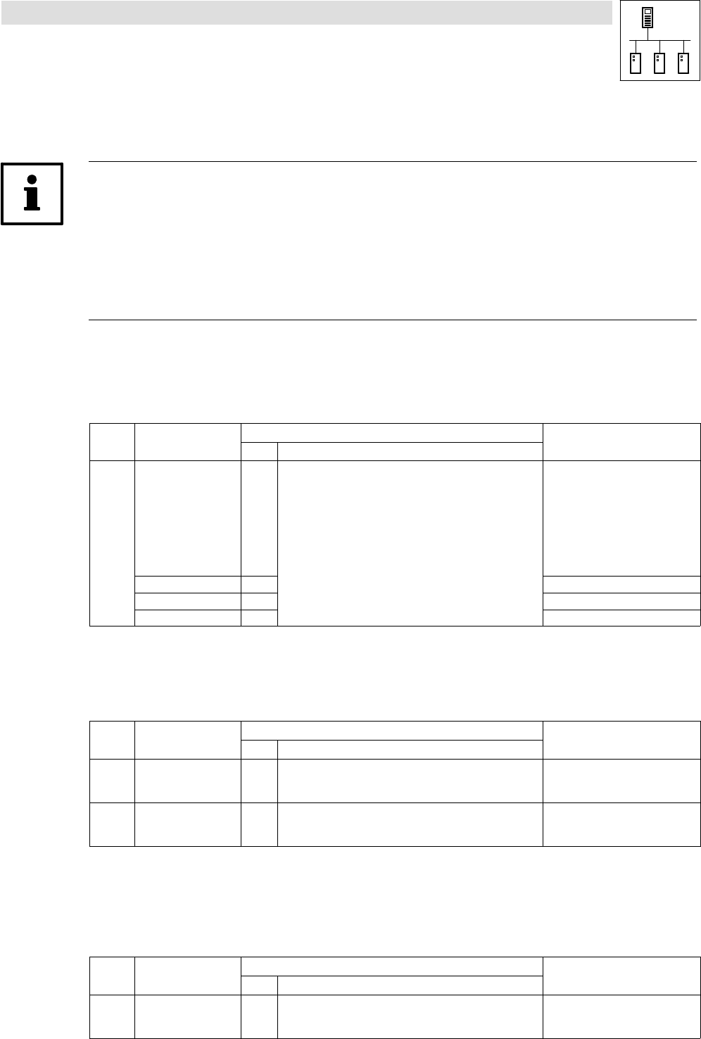
4.6.1 XCAN sync response
The response to the reception of a sync telegram can be configured via C2375:
Code LCD
Possible settings
IMPORTANT
Lenze Selection
C2375 XCAN Tx mode AIF−CAN sync response
· Selection of cycle time under
C2356
0 Sync with response
1 Sync without response
2 Event−controlled (with mask)/cyclically
3 Event−controlled (with mask)
with cyclic overlay
1 0 XCAN1_OUT
2 0 XCAN2_OUT
3 0 XCAN3_OUT
4.6.2 XCAN sync identifier
The transmission or reception identifiers of the sync telegram can be configured via C2367/C2368:
Code LCD
Possible settings
IMPORTANT
Lenze Selection
C2367 Sync Rx Id 128 1 {1} 256 XCAN sync Rx identifier
Receive identifier for the sync
telegram
C2368 Sync Tx Id 128 1 {1} 256 XCAN sync Tx identifier
Transmit identifier for the sync
telegram
4.6.3 XCAN sync Tx transmission cycle
The cycle time within which a sync telegram with the identifier set in C2368 is transmitted can be
configured via C2356/5:
Code LCD
Possible settings
IMPORTANT
Lenze Selection
C2356
5
Sync Tx time
0
0 {1 ms} 65535
0 = Off
XCAN sync time
Sync transmission telegram cycle