
Instruction Manual
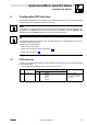
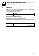
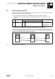
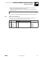
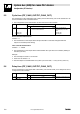
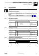
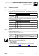
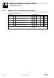
Table Of Contents
- System bus (CAN) for Lenze PLC devices
- This documentation is valid for ...
- Contents
- 1 Preface and general information
- 2 General information on the system bus (CAN)
- 2.1 Introduction
- 2.2 Interfaces of the Lenze PLCs for system bus connection
- 2.3 Identification of the nodes
- 2.4 Structure of the CAN telegram
- 2.5 Network management (NMT)
- 2.6 Transmission of process data
- 2.7 Transmitting parameter data
- 2.8 Free CAN objects
- 2.9 Application recommendations for the different CAN objects
- 2.10 Monitoring mechanisms
- 3 Configuration (system bus - CAN interface)
- 3.1 CAN baud rate
- 3.2 CAN boot-up
- 3.3 Node address (node ID)
- 3.4 Identifiers of the process data objects
- 3.5 Cycle time (CAN2_OUT/CAN3_OUT)
- 3.6 Delay time (CAN2_OUT/CAN3_OUT)
- 3.7 Synchronisation
- 3.8 Reset node
- 3.9 System bus management
- 3.10 Mapping indexes to codes
- 3.11 Remote parameterisation (gateway function)
- 3.12 Monitoring processes
- 3.13 Diagnostics
- 4 Configuration (AIF interface)
- 5 Configuration (FIF interface)
- 6 Configuration (CAN-AUX system bus interface)
- 7 CAN system blocks
- 8 FIF-CAN system blocks (only Drive PLC)
- 9 CAN-AUX system blocks (only ECSxA)
- 10 LenzeCanDrv.lib function library
- 10.1 Overview
- 10.2 Version identifiers of the function library
- 10.3 L_CanInit - initialising the CAN driver
- 10.4 L_CanClose - deactivating the CAN driver
- 10.5 L_CanGetStatus - querying the driver status
- 10.6 L_CanGetRelocCobId - querying the COB-ID range
- 10.7 L_CanPdoTransmit - transmitting a CAN object
- 10.8 L_CanPdoReceive - receiving a CAN object
- 11 LenzeCanDSxDrv.libfunction library
- 11.1 Overview
- 11.2 Version identifiers of the function library
- 11.3 L_CanDSxInitIndexCode - Configuration of index mapping
- 11.4 L_CanDSxOpen - initialising the CanDSx driver
- 11.5 L_CanDSxClose - deactivating the index mapping
- 11.6 L_CanDSxOpenHeartBeat - initialising a "Heartbeat"
- 11.7 L_CanDSxHeartBeat - carrying out a "Heartbeat"
- 11.8 L_CanDSxCloseHeartBeat - deactivating the "Heartbeat"
- 11.9 L_CanDSxOpenNodeGuarding - initialising the "Node Guarding"
- 11.10 L_CanDSxNodeGuarding - carrying out a "Node guarding"
- 11.11 L_CanDSxCloseNodeGuarding - deactivating the "Node Guarding"
- 12 Index
System bus (CAN) for Lenze PLC devices
Configuration (FIF interface)
5−7
l
PLC−Systembus EN 2.0
5.7 Synchronisation
Tip!
By means of the CAN_Synchronization SB, the internal time base of the PLC can be synchronised
with the arrival of the sync telegram.
Thus the internal calculating processes (e. g. control oriented processes) of the PLC can be
synchronised with the calculating processes of other nodes which can also process the sync
telegram.
Detailed information on the CAN_Synchronization SB can be found in chapter 7.7.
(^ 7−23)
5.7.1 FIF−CAN sync response
The response to the reception of a sync telegram can be configured via C2466:
Code LCD
Possible settings
IMPORTANT
Lenze Selection
C2466 Sync response 1 FIF−CAN sync response
0 No response No response
1 Response to sync PLC responds to a sync telegram
by sending the FIF−CAN1_OUT
object.
5.7.2 FIF−CAN sync identifier
The transmission or reception identifiers of the sync telegram can be configured via C2467/C2468:
Code LCD
Possible settings
IMPORTANT
Lenze Selection
C2467 Sync Rx Id 128 1 {1} 256 FIF−CAN sync Rx identifier
Receive identifier for the sync
telegram
C2468 Sync Tx Id 128 1 {1} 256 FIF−CAN sync Tx identifier
Send identifier for the sync
telegram
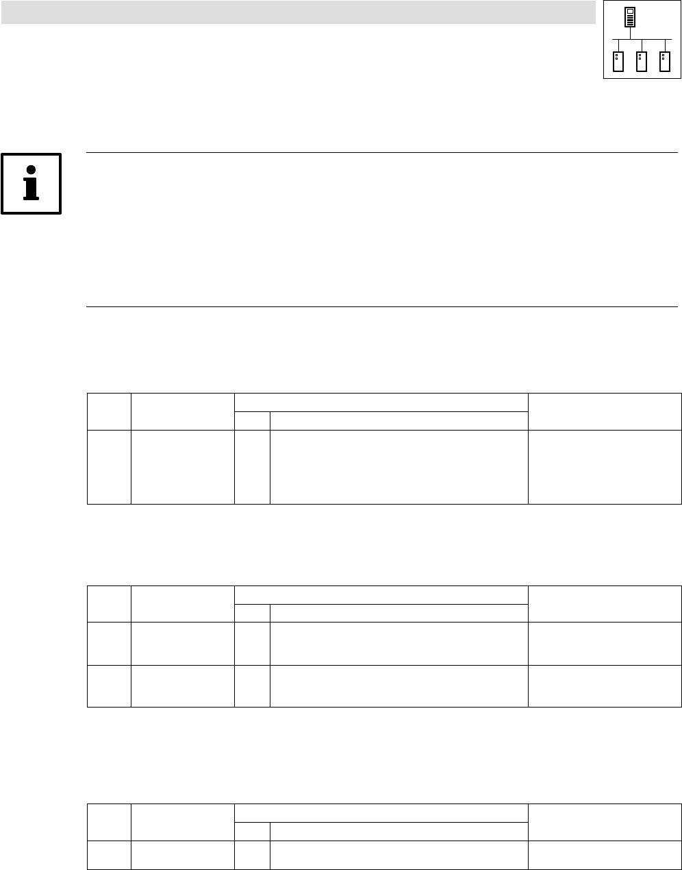
5.7.3 FIF−CAN sync Tx transmission cycle
The cycle time within which a sync telegram with the identifier set in C2468 is transmitted can be
configured via C2469:
Code LCD
Possible settings
IMPORTANT
Lenze Selection
C2469 Sync Tx time 0 0 {1 ms} 65000
0 = Off
FIF−CAN sync time
Sync transmission telegram cycle