
Instruction Manual
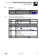
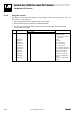
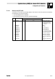

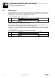
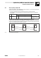
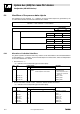
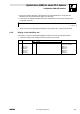
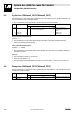
Table Of Contents
- System bus (CAN) for Lenze PLC devices
- This documentation is valid for ...
- Contents
- 1 Preface and general information
- 2 General information on the system bus (CAN)
- 2.1 Introduction
- 2.2 Interfaces of the Lenze PLCs for system bus connection
- 2.3 Identification of the nodes
- 2.4 Structure of the CAN telegram
- 2.5 Network management (NMT)
- 2.6 Transmission of process data
- 2.7 Transmitting parameter data
- 2.8 Free CAN objects
- 2.9 Application recommendations for the different CAN objects
- 2.10 Monitoring mechanisms
- 3 Configuration (system bus - CAN interface)
- 3.1 CAN baud rate
- 3.2 CAN boot-up
- 3.3 Node address (node ID)
- 3.4 Identifiers of the process data objects
- 3.5 Cycle time (CAN2_OUT/CAN3_OUT)
- 3.6 Delay time (CAN2_OUT/CAN3_OUT)
- 3.7 Synchronisation
- 3.8 Reset node
- 3.9 System bus management
- 3.10 Mapping indexes to codes
- 3.11 Remote parameterisation (gateway function)
- 3.12 Monitoring processes
- 3.13 Diagnostics
- 4 Configuration (AIF interface)
- 5 Configuration (FIF interface)
- 6 Configuration (CAN-AUX system bus interface)
- 7 CAN system blocks
- 8 FIF-CAN system blocks (only Drive PLC)
- 9 CAN-AUX system blocks (only ECSxA)
- 10 LenzeCanDrv.lib function library
- 10.1 Overview
- 10.2 Version identifiers of the function library
- 10.3 L_CanInit - initialising the CAN driver
- 10.4 L_CanClose - deactivating the CAN driver
- 10.5 L_CanGetStatus - querying the driver status
- 10.6 L_CanGetRelocCobId - querying the COB-ID range
- 10.7 L_CanPdoTransmit - transmitting a CAN object
- 10.8 L_CanPdoReceive - receiving a CAN object
- 11 LenzeCanDSxDrv.libfunction library
- 11.1 Overview
- 11.2 Version identifiers of the function library
- 11.3 L_CanDSxInitIndexCode - Configuration of index mapping
- 11.4 L_CanDSxOpen - initialising the CanDSx driver
- 11.5 L_CanDSxClose - deactivating the index mapping
- 11.6 L_CanDSxOpenHeartBeat - initialising a "Heartbeat"
- 11.7 L_CanDSxHeartBeat - carrying out a "Heartbeat"
- 11.8 L_CanDSxCloseHeartBeat - deactivating the "Heartbeat"
- 11.9 L_CanDSxOpenNodeGuarding - initialising the "Node Guarding"
- 11.10 L_CanDSxNodeGuarding - carrying out a "Node guarding"
- 11.11 L_CanDSxCloseNodeGuarding - deactivating the "Node Guarding"
- 12 Index
System bus (CAN) for Lenze PLC devices
Configuration (FIF interface)
5−11
l
PLC−Systembus EN 2.0
5.11 Diagnostics
The following codes can be used for diagnostics purposes:
Code Information displayed Information
C2459 FIF−CAN operating status Chapter 5.11.1 ^ 5−11
C2460 Number of the telegrams sent and received Chapter 5.11.2 ^ 5−12
C2461 Bus load (in %) Chapter 5.11.3 ^ 5−13
· Settings cannot be carried out via these codes.
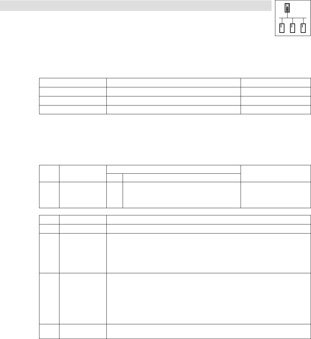
5.11.1 Function interface (FIF) operating status
Via C2459 you can have the operating status of the function interface displayed:
Code LCD
Possible settings
Information
Lenze Selection
C2459 CAN1 state
g
0 Operational
1 Pre−operational
2 Warning
3 Bus off
System bus status (FIF−CAN)
C2459 Operating status Information
0 Operational The system bus is fully functional. The PLC can transmit and receive parameter and process data.
1 Pre−operational The PLC can transmit and receive parameter data. Process data, however, are ignored.
A status change from Pre−Operational to Operational can be effected by:
· the CAN master ^ 3−2
· a reset node
– via C2458, if the PLC has been configured as a "quasi" master. ^ 5−8
– via the binary input signal "Reset node" at the FIF_CAN_Management SB ^ 7−20
2 Warning The PLC has received faulty telegrams and is only involved in the system bus passively, i. e. no data can be
sent from the PLC anymore.
Possible causes:
· Missing bus termination
· Non−sufficient shielding
· Differences in potential with regard to the earth connection of the control electronics
· Bus load too high
· PLC is not connected to the system bus.
3 Bus−off The PLC has disconnected from the system bus due to too many faultily received telegrams.
· The response to this status can be configured via C2484. ^ 5−9