
Instruction Manual
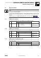
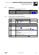
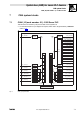
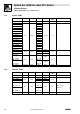
Table Of Contents
- System bus (CAN) for Lenze PLC devices
- This documentation is valid for ...
- Contents
- 1 Preface and general information
- 2 General information on the system bus (CAN)
- 2.1 Introduction
- 2.2 Interfaces of the Lenze PLCs for system bus connection
- 2.3 Identification of the nodes
- 2.4 Structure of the CAN telegram
- 2.5 Network management (NMT)
- 2.6 Transmission of process data
- 2.7 Transmitting parameter data
- 2.8 Free CAN objects
- 2.9 Application recommendations for the different CAN objects
- 2.10 Monitoring mechanisms
- 3 Configuration (system bus - CAN interface)
- 3.1 CAN baud rate
- 3.2 CAN boot-up
- 3.3 Node address (node ID)
- 3.4 Identifiers of the process data objects
- 3.5 Cycle time (CAN2_OUT/CAN3_OUT)
- 3.6 Delay time (CAN2_OUT/CAN3_OUT)
- 3.7 Synchronisation
- 3.8 Reset node
- 3.9 System bus management
- 3.10 Mapping indexes to codes
- 3.11 Remote parameterisation (gateway function)
- 3.12 Monitoring processes
- 3.13 Diagnostics
- 4 Configuration (AIF interface)
- 5 Configuration (FIF interface)
- 6 Configuration (CAN-AUX system bus interface)
- 7 CAN system blocks
- 8 FIF-CAN system blocks (only Drive PLC)
- 9 CAN-AUX system blocks (only ECSxA)
- 10 LenzeCanDrv.lib function library
- 10.1 Overview
- 10.2 Version identifiers of the function library
- 10.3 L_CanInit - initialising the CAN driver
- 10.4 L_CanClose - deactivating the CAN driver
- 10.5 L_CanGetStatus - querying the driver status
- 10.6 L_CanGetRelocCobId - querying the COB-ID range
- 10.7 L_CanPdoTransmit - transmitting a CAN object
- 10.8 L_CanPdoReceive - receiving a CAN object
- 11 LenzeCanDSxDrv.libfunction library
- 11.1 Overview
- 11.2 Version identifiers of the function library
- 11.3 L_CanDSxInitIndexCode - Configuration of index mapping
- 11.4 L_CanDSxOpen - initialising the CanDSx driver
- 11.5 L_CanDSxClose - deactivating the index mapping
- 11.6 L_CanDSxOpenHeartBeat - initialising a "Heartbeat"
- 11.7 L_CanDSxHeartBeat - carrying out a "Heartbeat"
- 11.8 L_CanDSxCloseHeartBeat - deactivating the "Heartbeat"
- 11.9 L_CanDSxOpenNodeGuarding - initialising the "Node Guarding"
- 11.10 L_CanDSxNodeGuarding - carrying out a "Node guarding"
- 11.11 L_CanDSxCloseNodeGuarding - deactivating the "Node Guarding"
- 12 Index
System bus (CAN) for Lenze PLC devices
Configuration (CAN−AUX interface)
6−12
l
PLC−Systembus EN 2.0
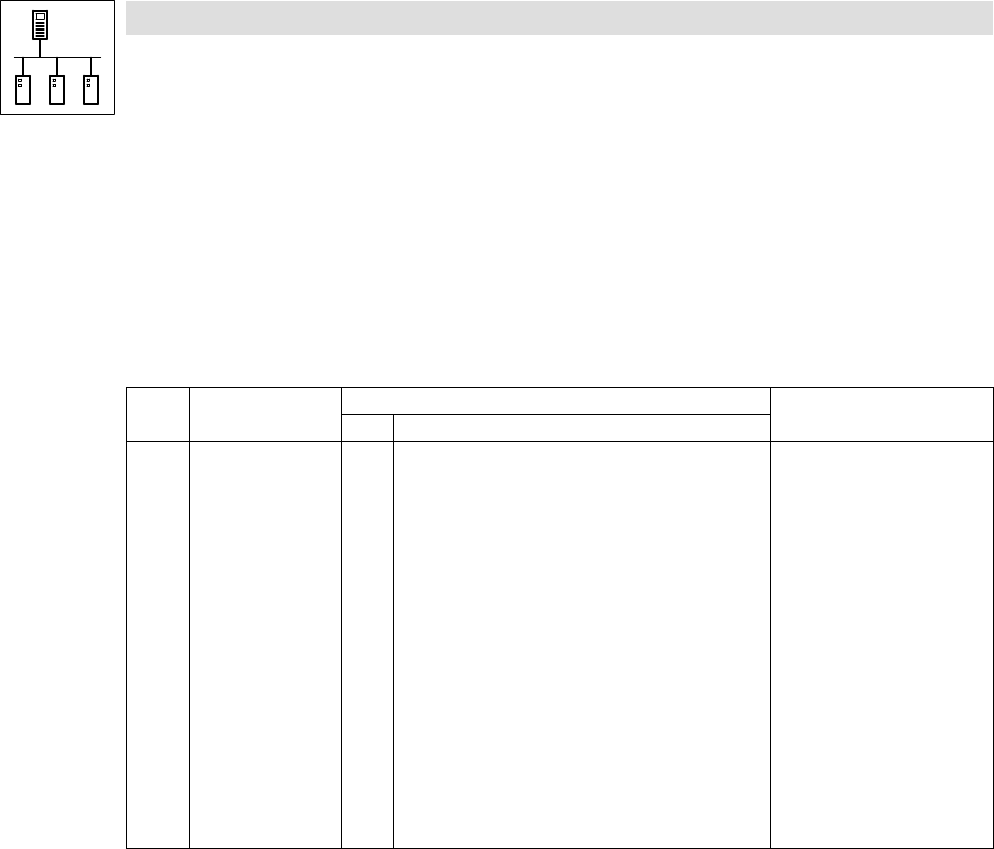
6.11.2 Telegram counter
Via C2460 you can have the number of the telegrams sent and received by the PLC via
CANaux1_IO ... CANaux3_IO.
· Only the telegrams which are valid for the PLC are counted.
· Each transmit and receive channel is evaluated separately.
· The max. counter content is 65535 (16 bit); if this value is exceeded, the corresponding
counter starts with 0 again.
Code LCD
Possible settings
Information
Lenze Selection
C2460 CAN message
g
0 {1} 65535 System bus telegram counter
(number of telegrams)
· For values > 65535 counting
restarts with 0.
1 Message OUT All sent
2 Message IN All received
3 Message OUT1 Sent on CANaux_OUT1
4 Message OUT2 Sent on CANaux_OUT2
5 Message OUT3 Sent on CANaux_OUT3
6 Message POUT1 Sent on parameter data channel 1
7 Message POUT2 Sent on parameter data channel 2
8 Message IN1 Received from CANaux_IN1
9 Message IN2 Received from CANaux_IN2
10 Message IN3 Received from CANaux_IN3
11 Message PIN1 Received from parameter data
channel 1
12 Message PIN2 Received from parameter data
channel 2