
Instruction Manual
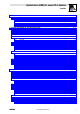
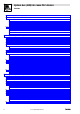
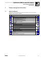
Table Of Contents
- System bus (CAN) for Lenze PLC devices
- This documentation is valid for ...
- Contents
- 1 Preface and general information
- 2 General information on the system bus (CAN)
- 2.1 Introduction
- 2.2 Interfaces of the Lenze PLCs for system bus connection
- 2.3 Identification of the nodes
- 2.4 Structure of the CAN telegram
- 2.5 Network management (NMT)
- 2.6 Transmission of process data
- 2.7 Transmitting parameter data
- 2.8 Free CAN objects
- 2.9 Application recommendations for the different CAN objects
- 2.10 Monitoring mechanisms
- 3 Configuration (system bus - CAN interface)
- 3.1 CAN baud rate
- 3.2 CAN boot-up
- 3.3 Node address (node ID)
- 3.4 Identifiers of the process data objects
- 3.5 Cycle time (CAN2_OUT/CAN3_OUT)
- 3.6 Delay time (CAN2_OUT/CAN3_OUT)
- 3.7 Synchronisation
- 3.8 Reset node
- 3.9 System bus management
- 3.10 Mapping indexes to codes
- 3.11 Remote parameterisation (gateway function)
- 3.12 Monitoring processes
- 3.13 Diagnostics
- 4 Configuration (AIF interface)
- 5 Configuration (FIF interface)
- 6 Configuration (CAN-AUX system bus interface)
- 7 CAN system blocks
- 8 FIF-CAN system blocks (only Drive PLC)
- 9 CAN-AUX system blocks (only ECSxA)
- 10 LenzeCanDrv.lib function library
- 10.1 Overview
- 10.2 Version identifiers of the function library
- 10.3 L_CanInit - initialising the CAN driver
- 10.4 L_CanClose - deactivating the CAN driver
- 10.5 L_CanGetStatus - querying the driver status
- 10.6 L_CanGetRelocCobId - querying the COB-ID range
- 10.7 L_CanPdoTransmit - transmitting a CAN object
- 10.8 L_CanPdoReceive - receiving a CAN object
- 11 LenzeCanDSxDrv.libfunction library
- 11.1 Overview
- 11.2 Version identifiers of the function library
- 11.3 L_CanDSxInitIndexCode - Configuration of index mapping
- 11.4 L_CanDSxOpen - initialising the CanDSx driver
- 11.5 L_CanDSxClose - deactivating the index mapping
- 11.6 L_CanDSxOpenHeartBeat - initialising a "Heartbeat"
- 11.7 L_CanDSxHeartBeat - carrying out a "Heartbeat"
- 11.8 L_CanDSxCloseHeartBeat - deactivating the "Heartbeat"
- 11.9 L_CanDSxOpenNodeGuarding - initialising the "Node Guarding"
- 11.10 L_CanDSxNodeGuarding - carrying out a "Node guarding"
- 11.11 L_CanDSxCloseNodeGuarding - deactivating the "Node Guarding"
- 12 Index
System bus (CAN) for Lenze PLC devices
Preface and general information
1.1 About this Manual
1−1
L
PLC−Systembus EN 2.0
1 Preface and general information
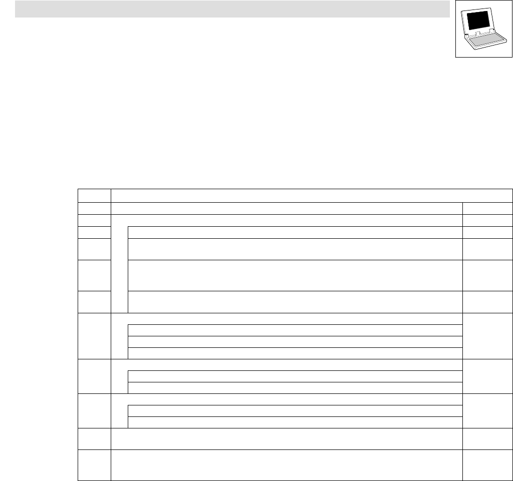
1.1 About this Manual
This Manual contains information on the system bus interfaces of the Lenze PLC devices
9300 Servo PLC, Drive PLC and ECSxA.
Chapter Content
2 General information on the system bus (CAN) ^ 2−1
Configuration
3
Integrated "CAN" system bus interface ^ 3−1
4
Optional system bus interface via automation interface (AIF)
and corresponding fieldbus module (e. g. 2175)
^ 4−1
5
Optional system bus interface via function interface (FIF)
and corresponding function module (e. g. CAN−I/O system bus)
· Only for Drive PLC!
^ 5−1
6
Integrated "CAN−AUX" system bus interface
· Only for ECSxA!
^ 6−1
7
CAN system blocks
^ 7−1
CAN objects (CAN1_IO ... CAN3_IO)
CAN synchronisation (CAN_Synchronization)
CAN management (CAN_Management)
8
FIF−CAN system blocks (only Drive PLC)
^ 8−1
CAN objects (FIF_CAN1_IO ... FIF_CAN3_IO)
CAN management (FIF_CAN_Management)
9
CAN−AUX system blocks (only ECSxA)
^ 9−1
CAN objects (CANaux1_IO ... CANaux3_IO)
CAN management (CANaux_Management)
10
LenzeCanDrv.lib function library
· Free CAN objects
^ 10−1
11
LenzeCanDSxDrv.libfunction library
· Mapping indexes to codes
· "Heartbeat" and "Node Guarding"monitoring mechanisms
^ 11−1