
Instruction Manual
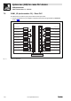
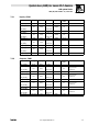

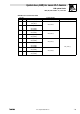


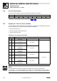
Table Of Contents
- System bus (CAN) for Lenze PLC devices
- This documentation is valid for ...
- Contents
- 1 Preface and general information
- 2 General information on the system bus (CAN)
- 2.1 Introduction
- 2.2 Interfaces of the Lenze PLCs for system bus connection
- 2.3 Identification of the nodes
- 2.4 Structure of the CAN telegram
- 2.5 Network management (NMT)
- 2.6 Transmission of process data
- 2.7 Transmitting parameter data
- 2.8 Free CAN objects
- 2.9 Application recommendations for the different CAN objects
- 2.10 Monitoring mechanisms
- 3 Configuration (system bus - CAN interface)
- 3.1 CAN baud rate
- 3.2 CAN boot-up
- 3.3 Node address (node ID)
- 3.4 Identifiers of the process data objects
- 3.5 Cycle time (CAN2_OUT/CAN3_OUT)
- 3.6 Delay time (CAN2_OUT/CAN3_OUT)
- 3.7 Synchronisation
- 3.8 Reset node
- 3.9 System bus management
- 3.10 Mapping indexes to codes
- 3.11 Remote parameterisation (gateway function)
- 3.12 Monitoring processes
- 3.13 Diagnostics
- 4 Configuration (AIF interface)
- 5 Configuration (FIF interface)
- 6 Configuration (CAN-AUX system bus interface)
- 7 CAN system blocks
- 8 FIF-CAN system blocks (only Drive PLC)
- 9 CAN-AUX system blocks (only ECSxA)
- 10 LenzeCanDrv.lib function library
- 10.1 Overview
- 10.2 Version identifiers of the function library
- 10.3 L_CanInit - initialising the CAN driver
- 10.4 L_CanClose - deactivating the CAN driver
- 10.5 L_CanGetStatus - querying the driver status
- 10.6 L_CanGetRelocCobId - querying the COB-ID range
- 10.7 L_CanPdoTransmit - transmitting a CAN object
- 10.8 L_CanPdoReceive - receiving a CAN object
- 11 LenzeCanDSxDrv.libfunction library
- 11.1 Overview
- 11.2 Version identifiers of the function library
- 11.3 L_CanDSxInitIndexCode - Configuration of index mapping
- 11.4 L_CanDSxOpen - initialising the CanDSx driver
- 11.5 L_CanDSxClose - deactivating the index mapping
- 11.6 L_CanDSxOpenHeartBeat - initialising a "Heartbeat"
- 11.7 L_CanDSxHeartBeat - carrying out a "Heartbeat"
- 11.8 L_CanDSxCloseHeartBeat - deactivating the "Heartbeat"
- 11.9 L_CanDSxOpenNodeGuarding - initialising the "Node Guarding"
- 11.10 L_CanDSxNodeGuarding - carrying out a "Node guarding"
- 11.11 L_CanDSxCloseNodeGuarding - deactivating the "Node Guarding"
- 12 Index
System bus (CAN) for Lenze PLC devices
CAN system blocks
7.1 CAN1_IO (node number: 31) − 9300 Servo PLC
7−5
L
PLC−Systembus EN 2.0
7.1.5 Transferring status and control information of the device control
Via the user data bytes 1 and 2, you can exchange status and control information of the device
control (DCTRL) between different 9300 Servo PLCs via the system bus (CAN) in a simple manner.
Sending the status word of the DCTRL SB
Connect the variable DCTRL_wStat of the DCTRL SB to the variable CAN1_wDctrlStat to transfer
the status word of the DCTRL SB via the user data bytes 1 and 2.
Tip!
In addition to signals such as IMP and CINH, the SB status word DCTRL contains some freely
assignable signals which can be overwritten via the variables DCTRL_bStateB.._b of the DCTRL SB.
Detailed information on the DCTRL SB can be found in the "9300 Servo PLC" Online Manual.
Transferring the control word to the DCTRL SB
Connect the variable CAN1_wDctrlCtrl to the variable DCTRL_wCAN1Ctrl of the DCTRL SB to
transfer the control word received via the user data bytes 1 and 2 to the DCTRL SB.
Tip!
The control signals for the functions quick stop (QSP), DISABLE, CINH, TRIP−SET, and TRIP−RESET
can be additionally read out and processed via the following variables:
· CAN1_bCtrlQuickstop_b
· CAN1_bCtrlDisable_b
· CAN1_bCtrlInhibit_b
· CAN1_bCtrlTripSet_b
· CAN1_bCtrlTripReset_b
The remaining 11 bits (CAN1_bCtrlB..._b) can be used for controlling further functions/function
blocks.