Ä.=
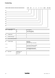
Product key DISCO variable speed drive with rear−mounted gearbox − D − Lengend for the product key Gearbox type Gearbox size Number of stages Disco variable speed drive Output design Drive size 2 GST GKS GSS Helical gearbox Helical−bevel gearbox Helical−worm gearbox V H S Solid shaft Hollow shaft Hollow shaft with shrink disk A B C Foot mounting, with centring Foot mountin, without centring Without foot, with centring R K l Wi
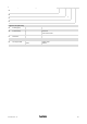
11. DISCO variable speed drive without rear−mounted gearbox 7 0 0 0. Lengend for the product key Product group Product family DISCO size Free output shaft BA 11.5032−EN 3.
Nameplate DISCO variable speed drive without rear−mounted gearbox GT−DISCO−002.iso Pos. Contents 1 Production location / Name of product 2 Gearbox type 3 Order number 4 Rated speed:drive | output 5 Year of manufacture/ week of manufacture 6 Rated torque 7 Material number 8 Power DISCO variable speed drive with rear−mounted gearbox DISCO nameplate Nameplate of rear−mounted gearbox GT−DISCO−001.iso Pos.
Document history Material number Version Description 410700 1.0 09/1999 TD09 Completely revised 483298 1.1 12/2003 TD09 Revised description of the mounting position and position of the system blocks 13251318 2.0 10/2007 TD09 New nameplate: Compact unit and DISCO version Table of oil grades and new representation of the positions of ventilation, oil filler plug and oil drain plug 3.0 12/2008 TD09 New edition due to reorganisation of the company .=
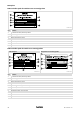
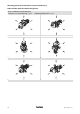
Mounting position (A−F) and position of system modules (1−6) DISCO variable speed drive with helical gearbox GST − 1D VDR (foot on variable speed drive) Terminal box: 2, 3, 4, 5 Spindle housing: 2, 3, 4, 5 Handwheel/adjusting device: 2, 3, 4, 5 A B C D E F 6 l BA 11.5032−EN 3.
GST − D Terminal box: 2, 3, 4, 5 Spindle housing: 2, 3, 4, 5 Handwheel/adjusting device: 2, 3, 4, 5 A B C D E F BA 11.5032−EN 3.
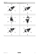
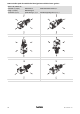
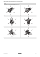
DISCO variable speed drive with helical−bevel gearbox and helical−worm gearbox GKS − D / GSS − D Solid shaft: 2, 3, 8 (3+5) Hollow shaft: 0 Hollow shaft with shrink disc: 3, 5 Flange: 2, 3, 8 (3+5) Without flange: 0 Terminal box: 2, 3, 4, 5 Spindle housing: 2, 3, 4, 5 Handwheel/adjusting device: 2, 3, 4, 5 A B C D E F 8 l BA 11.5032−EN 3.
DISCO variable speed drive without rear−mounted gearbox 11.7 0 Terminal box: 2, 3, 4, 5 Handwheel/adjusting device: 2, 3, 4, 5 A B C D E F BA 11.5032−EN 3.
i 1 2 3 4 5 6 7 10 Contents Preface and general information . . . . . . . . . . . . . . . . . . . . . . . . . . . . . . . . . . . . . . . . . . . . 12 1.1 About these Operating Instructions . . . . . . . . . . . . . . . . . . . . . . . . . . . . . . . . . . . . . 12 1.2 Terminology used . . . . . . . . . . . . . . . . . . . . . . . . . . . . . . . . . . . . . . . . . . . . . . . . . . . . 12 1.3 Scope of supply . . . . . . . . . . . . . . . . . . . . . . . . . . . . . . . . . . . . . . .
Contents i 8 Troubleshooting and fault elimination . . . . . . . . . . . . . . . . . . . . . . . . . . . . . . . . . . . . . . . 28 9 Disposal . . . . . . . . . . . . . . . . . . . . . . . . . . . . . . . . . . . . . . . . . . . . . . . . . . . . . . . . . . . . . . . . . . 29 10 Appendix . . . . . . . . . . . . . . . . . . . . . . . . . . . . . . . . . . . . . . . . . . . . . . . . . . . . . . . . . . . . . . . . 30 10.1 Spare−parts list . . . . . . . . . . . . . . . . . . . . . . . . . . . . .
1 Preface and general information About these Operating Instructions 1 Preface and general information 1.1 About these Operating Instructions 1.2 1.3 12 ƒ These Operating Instructions provide information about safety−relevant work on and with DISCO variable speed drives. They contain safety instructions which must be observed. ƒ All personnel working on and with DISCO variable speed drives must have these Operating Instructions available and observe the information and notes relevant for them.
Preface and general information 1 Lenze drive systems Labelling 1.4 Lenze drive systems 1.4.1 Labelling Lenze drive systems are uniquely designated by the content of their nameplates.
2 Safety instructions Personnel responsible for safety 2 Safety instructions 2.1 Personnel responsible for safety Operator ƒ An operator is any natural or legal person who uses the drive system or on behalf of whom the drive system is used. ƒ The operator or his safety officer must ensure – that all relevant regulations, instructions and legislation are observed. – that only qualified personnel work with and on the drive system.
Safety instructions 2 Definition of notes used 2.
3 Technical data Product features 3 3.1 Technical data ƒ The most important technical data are provided on the nameplate (layout and contents ^ page 4). ƒ The product catalogues contain further technical data. Product features GT−DISCO−005.iso Fig.
Technical data 3 Product features multi−stage helical, conical or worm gearboxes, can be used to adjust output speed to the requirements of the application. ( Stop! The DISCO must only be changed to a fasterspeed while it is running! Otherwise, the DISCO could be damaged! Changing to a slowerspeed is allowed while the DISCO is standing still. BA 11.5032−EN 3.
3 Technical data Transport weights 3.
Technical data 3 Operating conditions Temperatures 3.3 Operating conditions 3.3.1 Temperatures ƒ DISCO: permissible ambient temperature −15 bis +40°C ƒ Rear−mounted gearbox (see Operating Instructions for the gearbox) ƒ Motor (see temperature class for the motor) The operating temperature is determined by the power loss, the ambient temperature and the cooling system! 3.3.2 BA 11.5032−EN Ambient conditions ƒ DISCO variable speed drives are dust and hose−proof.
4 Mechanical installation Storage 4 Mechanical installation } Danger! Only transport the drive with transport equipment or hoists which are suitable for this load (see transport weights, chapter 3.2). Ensure a safe fixing. Avoid shocks! The motors attached to the gearbox are partially equipped with eyebolts. These are exclusively determined for motor/gearbox mounting and dismounting and must not be used for the complete geared motor! 4.
Electrical installation 5 Electrical adjusting device 5 Electrical installation { Danger! Electrical connections must only be carried out by skilled personnel! { Danger! Always earth the drive! If it is not possible to earth it via attached items (e.g. the motor) then the gearbox must be earthed! 5.1 Connection of main motor To connect the motor correctly, you must follow: 5.
5 Electrical installation Electrical adjusting device Operational check 4. The adjustment motor and actuator must stop. 5. If the actuator and adjustment motor do not stop, reverse the polarity of the adjustment motor. Adjustment motor in position 3 / limit−switch box in position 5 1. Switch on the DISCO. 2. Increase the speed: clockwise rotation of the actuator in the limit−switch housing. 3. While the speed is increased, activate the limit−switch S3 with an insulated screwdriver. 4.
Commissioning and operation 6 Before switching on 6 Commissioning and operation ( Stop! Commissioning of the drive only by qualified staff! 6.1 Before switching on Check: ƒ Is the mechanical fixing o.k.? ƒ Are the electrical connections o.k.? ƒ Are all rotating parts and surfaces that may become hot protected against contact? ƒ For gearboxes with breathing: – Is the plug removed from the breather screw? ) 6.
7 Maintenance Oil filling quantities for DISCO gearboxes 7 Maintenance The DISCO drives are supplied with oil filling. ) Note! Lubricating instructions for rear−mounted gearboxes, see Operating Instructions of the gearbox. ƒ We recommend to check the oil level regularly! ƒ If you use an oil not listed in Tab. 2, we recommend lubricants with the following technical values: – Viscosity: 32mm2/s ±10% at 40°C – Flash point: ~ 210°C – Pourpoint: ~ −30°C – FZG test A8.
Maintenance 7 Oil filling quantities for DISCO gearboxes Oil grades for DISCO variable speed drives 7.1.1 Oil grades for DISCO variable speed drives Manufacturer Oil types DISCO lifetime oil Shell Tegula V 32 Astron HLP 32 / Pentran 32 Shell LAMORA HLP 32 RENOLIN MR 10 VG 32 / RENOFLUID TF 1500 Degol GB 32 OSO 32 / BLASIA 32 Energol HL−XP 32 / Energol HLP−HM 32 Hyspin AWS 32 / Hyspin SP 32 TORQUE FLUID N 45 Wiolan HF 32 Rando Oil HD A−32 Tab. 2 BA 11.5032−EN 3.
7 Maintenance Oil filling quantities for DISCO gearboxes Breather position, oil filling screw and drain plug 7.1.2 Breather position, oil filling screw and drain plug GT−DISCO−007.cdr Oil filling for gearboxes without ventilation Ventilation / oil filler plug Oil drain plug Oil control plug 1) Facing the housing 2) In case of a position of the handle different from the shown one, the positions are facing the housing respectively 26 l BA 11.5032−EN 3.
Maintenance 7 Maintenance intervals 7.2 Maintenance intervals ƒ The mechanical power transmission system is maintenance−free. ƒ No oil change when DISCO lifetime oil is used. If other oils are used, an oil change is necessary after every 2000 hours of operation. ƒ Shaft seal rings: – The operating life depends on the conditions of use. – Replace leaking shaft seals to prevent further damage. ( Stop! For drive systems: Also observe the maintenance intervals for the other drive components! 7.
8 Troubleshooting and fault elimination 8 Troubleshooting and fault elimination Fault Drive does not start Motor runs, gearbox does not Unusual running noise Excessive temperature Loose fixing elements 28 Possible cause Remedy Voltage supply interrupted Check connection Faulty electrical connection Check that supply voltage matches nameplate data Excessive load Reduce load Check drive−machine assignment Coupling components are missing or defective Check mounting Gearbox is defective Inf
Disposal 9 9 Disposal Protect the environment! Valuable materials can be recycled. What? Transport material BA 11.5032−EN 3.
10 Appendix Spare−parts list DISCO variable speed drive size 02 10 Appendix 10.1 Spare−parts list 10.1.1 DISCO variable speed drive size 02 1.07 1.03 4471 4401 4420 4410 1.08 201 4421 4424 4423 4425 220 221 30 l BA 11.5032−EN 3.
Appendix Pos. Name Pos. Name Pos. Name 0.25 Seal 3.19 Socket 4.37 Dowel pin 0.26 Seal 3.26 Socket 4.38 Dowel pin 0.28 Hexagon head cap screw 3.27 Pressure spring 4.39 Set screw 0.29 Locking washer for sizes 02−03 3.28 Deep−groove ball bearing 4.40 Set screw Spring washer for sizes 04−07 3.29 Deep−groove ball bearing 4.41 Set screw 0.30 Cheese head screw 3.32 Deep−groove ball bearing 4.42 Conical plug 0.31 Spring washer 3.36 Shaft sealing ring 4.
10 Appendix DISCO variable speed drive size 03 10.1.2 DISCO variable speed drive size 03 4471 4401 4410 1.08 201 4420 4421 4422 4423 4425 220 221 32 l BA 11.5032−EN 3.
Appendix Pos. Name Pos. Name Pos. Name 0.25 Seal 3.09 Pinion cage 4.28 Circlip 0.26 Seal 3.10 Slide block 4.29 Locking ring 0.28 Hexagon head cap screw 3.11 Socket 4.31 Shim ring 0.29 Locking washer for sizes 02−03 3.12 Washer 4.32 Seeger ring Spring washer for sizes 04−07 3.14 Clutch collar 4.33 Dowel pin 0.30 Cheese head screw 3.15 Ball retainer ring 4.34 Dowel pin 0.31 Spring washer 3.16 Clutch thrust collar 4.35 Dowel pin 0.40 Oil sight glass 3.
10 Appendix DISCO variable speed drive size 04−07 10.1.3 DISCO variable speed drive size 04−07 4471 4401 4421 4410 1.08 201 4420 220 221 34 4425 4423 4422 l BA 11.5032−EN 3.
Appendix Pos. Name Pos. Name Pos. Name 0.25 Seal 3.09 Pinion cage 4.28 Circlip 0.26 Seal 3.10 Slide block 4.29 Locking ring 0.28 Hexagon head cap screw 3.11 Socket 4.31 Shim ring 0.29 Locking washer for sizes 02−03 3.12 Washer 4.32 Seeger ring Spring washer for sizes 04−07 3.14 Clutch collar 4.33 Dowel pin 0.30 Cheese head screw 3.15 Ball retainer ring 4.34 Dowel pin 0.31 Spring washer 3.16 Clutch thrust collar 4.35 Dowel pin 0.40 Oil sight glass 3.
10 Appendix DISCO variable speed drive size 08−18 10.1.4 4401 DISCO variable speed drive size 08−18 4471 4421 4410 201 4420 1.08 220 221 36 4422 4424 4423 4425 l BA 11.5032−EN 3.
Appendix Pos. Name Pos. Name Pos. Name 0.25 Seal 3.01 Cover 4401 Flange 0.26 Seal 3.03 Flange 4410 Shaft 0.28 Hexagon head cap screw 3.05 Shaft 4420 Deep−groove ball bearing 0.29 Locking washer for sizes 02−03 3.08 Hub 4421 Shaft sealing ring Spring washer for sizes 04−07 3.09 Pinion cage 4422 Circlip 0.30 Cheese head screw 3.10 Slide block 4423 Deep−groove ball bearing 0.31 Spring washer 3.11 Socket 4424 Adapter disc 0.40 Oil sight glass 3.
10 Appendix Speed adjustment mechanism, size 02−07 10.1.5 38 Speed adjustment mechanism, size 02−07 l BA 11.5032−EN 3.
Appendix Pos. Name Pos. Name 4.00 Spindle housing assembly 5.00 Limit−switch assembly 4.01 Spindle housing 5.01 Housing 4.02 Housing 5.02 Housing 4.03 Spindle 5.03 Actuator 4.04 Guide part 5.04 Board assembly 4.05 Shaft 5.05 Plate 4.06 Ball headed pin 5.06 Microswitch 4.08 Socket 5.07 Potentiometer 4.09 Adapter 5.08 Worm 4.10 Small worm−geared motor 5.09 Screw joint 4.12 Handwheel 5.10 Screw joint 4.13 Rotation−direction indicator 5.11 Set screw 4.
10 Appendix Speed adjustment mechanisms, size 08−18 10.1.6 40 Speed adjustment mechanisms, size 08−18 l BA 11.5032−EN 3.
Appendix Pos. Name Pos. Name 1.01 Housing 4.53 Spring washer 1.02 Thrust collar 4.55 Hub 1.03 Foot 4.56 Bell housing 1.04 Set screw 4.57 Handle 1.05 Seal−Lock hexagon nut 4.58 Hexagon head cap screw 1.06 Dowel pin 5.00 Limit−switch assembly 1.07 Cheese head screw 5.01 Housing 1.08 Oil sight glass 5.02 Housing 4.00 Spindle housing assembly 5.03 Actuator 4.01 Spindle housing 5.04 Board assembly 4.02 Housing 5.05 Plate 4.03 Spindle 5.06 Microswitch 4.
! 42 Notes l BA 11.5032−EN 3.
Notes BA 11.5032−EN 3.
Q BA 11.5032−EN 3.0 12/2008 © 2008 TD09 Lenze Drives GmbH Postfach 10 13 52 D−31763 Hameln Germany ( ( Service Ê Service +49 (0)51 54 / 82−0 E−Mail Internet Lenze@Lenze.de www.Lenze.