Accessories EtherCAT® 13429553 Ä.
Contents ________________________________________________________________ 1 1.1 1.2 1.3 1.
Contents ________________________________________________________________ 7 7.1 7.2 7.
1 About this documentation ________________________________________________________________ 1 About this documentation Contents This documentation only contains descriptions for the E84AYCET communication module (EtherCAT®). Note! This documentation supplements the Mounting Instructions supplied with the communication module and the "Inverter Drives 8400" Hardware Manual. The features and functions of the communication module are described in detail. Examples illustrate typical applications.
1 About this documentation ________________________________________________________________ Target group This documentation is intended for all persons who plan, install, commission and maintain the networking and remote servicing of a machine. Tip! Current documentation and software updates with regard to Lenze products can be found in the download area at: www.Lenze.
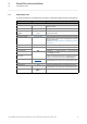
1 About this documentation 1.1 Document history ________________________________________________________________ 1.1 Document history Version 6 Description 1.0 08/2009 TD17 First edition 2.0 10/2009 TD17 Amendment of the information on the synchronisation via the fieldbus and general revision 3.0 04/2010 TD17 General revision 4.0 11/2010 TD17 Information about the EtherCAT register "AL Status Code" ( 58) supplemented. 4.
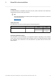
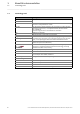
1 About this documentation 1.2 Conventions used ________________________________________________________________ 1.2 Conventions used This documentation uses the following conventions to distinguish different types of information: Type of information Identification Examples/notes Numbers Decimal separator Hexadecimal Binary • Nibble Point 0x[0 ... 9, A ... F] In inverted commas Point In general, the decimal point is used. Example: 1234.56 Example: 0x60F4 Example: ’100’ Example: ’0110.
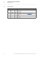
1 About this documentation 1.3 Terminology used ________________________________________________________________ 1.3 Terminology used Term Meaning Inverter Lenze inverters of the "Inverter Drives 8400" series Standard device Code Parameter which serves to parameterise and monitor the drive. In normal usage, the term is usually referred to as "Index". Subcode If a code contains several parameters, they are stored in so-called "subcodes".
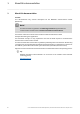
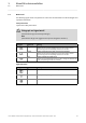
1 About this documentation 1.4 Notes used ________________________________________________________________ 1.
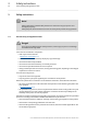
2 Safety instructions 2.1 General safety and application notes ________________________________________________________________ 2 Safety instructions Note! Always observe the specified safety measures to avoid severe injury to persons and damage to property! Always keep this documentation to hand in the vicinity of the product during operation. 2.
2 Safety instructions 2.2 Device- and application-specific safety instructions ________________________________________________________________ 2.2 Device- and application-specific safety instructions • During operation, the communication module must be firmly connected to the standard device. • With external voltage supply, always use a separate power supply unit, safely separated to EN 61800-5-1 in every control cabinet (SELV/PELV). • Only use cables that correspond to the given specifications.
3 Product description 3.1 Application as directed ________________________________________________________________ 3 Product description 3.1 Application as directed The communication module ... • is an accessory module which can be used with the following standard devices: Product series Type designation From software version Inverter Drives 8400 StateLine E84AVSCxxxxx 03.00 Inverter Drives 8400 HighLine E84AVHCxxxxx 02.00 Inverter Drives 8400 TopLine E84AVTCxxxxx 01.
3 Product description 3.3 Product features ________________________________________________________________ 3.3 Product features • Interface module for the EtherCAT communication system to the expansion slots of the Inverter Drives 8400 • The communication module can be supplied internally by the standard device and externally via a separate voltage source.
3 Product description 3.4 Terminals and interfaces ________________________________________________________________ 3.
4 Technical data 4.1 General data and operating conditions ________________________________________________________________ 4 Technical data 4.
4 Technical data 4.2 Protective insulation ________________________________________________________________ 4.2 Protective insulation Danger! Dangerous voltage If Inverter Drives 8400 are used on a phase earthed mains with a rated mains voltage ≥ 400 V, external measures need to be implemented in order to provide reliable protection against accidental contact.
4 Technical data 4.2 Protective insulation ________________________________________________________________ The following illustration ... • shows the arrangement of the terminal strips and the separate potential areas of the inverter. • serves to determine the decisive protective insulation between two terminals located in differently insulated separate potential areas. Bus Ext.
4 Technical data 4.2 Protective insulation ________________________________________________________________ Example Which type of protective insulation is used between the bus terminal of the device module in slot MCI and the mains terminal X100? The separate potential area with the better protective insulation is decisive. • The separate potential area of the bus terminal of the device module has a "basic insulation". • The separate potential area of the mains terminal has a "reinforced insulation".
4 Technical data 4.3 Protocol data ________________________________________________________________ 4.3 Protocol data Area Values Process data words 1 ... 16 process data words per direction (max. 32 bytes, 16 bits/word) Parameter data (mailbox size for CoE Max. 128 bytes transfer) 4.4 Communication time The communication time is the time between the start of a request and the arrival of the corresponding response. The communication times in the EtherCAT network depend on the ...
4 Technical data 4.5 Dimensions ________________________________________________________________ 4.5 Dimensions E84YCET001B [4-2] Dimensions Type E84AYCET 20 Dimensions [mm] a b c c1 67 50 57 8 Lenze · E84AYCET communication module (EtherCAT) · Communication Manual · DMS 5.
5 Installation ________________________________________________________________ 5 Installation Stop! Electrostatic discharge Electronic components in the communication module can be damaged or destroyed by electrostatic discharge. Possible consequences: • The communication module is defective. • Fieldbus communication is faulty or not possible. Protective measures: Before touching the module, make sure that you are free of electrostatic charge.
5 Installation 5.1 Mechanical installation ________________________________________________________________ 5.1 Mechanical installation The communication module can be plugged into the MCI slot or removed while the frequency inverter is switched on. When the module is plugged in, it is recognised automatically and checked for plausibility regarding its function and version. 5.1.1 Mounting for standard devices 0.25 kW and 0.37 kW E84YCPM002D [5-1] Mounting for standard devices 0.25 kW and 0.
5 Installation 5.1 Mechanical installation ________________________________________________________________ 5.1.2 Mounting for standard devices from 0.55 kW onwards E84YCPM002A [5-2] Mounting for standard devices from 0.55 kW onwards Mounting steps 1. Slightly impress the pressure surface of the top side of the MCI slot cover of the standard device (1). 2. Bend the cover forward and remove it from the standard device (2). 3.
5 Installation 5.1 Mechanical installation ________________________________________________________________ 5.1.3 Replacing the communication module E84YCPM002B [5-3] Replacing the communication module Mounting steps 1. Loosen the securing screw for the communication module at the standard device (1). 2. Remove the communication module from the MCI slot of the standard device (2). 3. Insert the new communication module into the MCI slot of the standard device (3). 4.
5 Installation 5.2 Electrical installation ________________________________________________________________ 5.2 Electrical installation 5.2.1 Documentation for the standard device, control system, plant/machine Observe the notes and wiring instructions stated. EMC-compliant wiring In typical systems, standard shielding is sufficient for Ethernet cables.
5 Installation 5.2 Electrical installation ________________________________________________________________ 5.2.2 Network topology An EtherCAT frame is sent through a pair of wires from the master to the slaves. The frame is forwarded from slave to slave until it has passed through all the devices. Finally, the last slave returns the frame to the master through a second pair of wires. In this way, EtherCAT always forms a logic ring topology, irrespective of the topology used.
5 Installation 5.2 Electrical installation ________________________________________________________________ 5.2.3 EtherCAT connection EtherCAT is connected via the RJ45 sockets X246 (IN) and X247 (OUT). E84YCET001E [5-6] EtherCAT connection A standard Ethernet patch cable is suitable for connecting the communication module to the EtherCAT fieldbus.
5 Installation 5.2 Electrical installation ________________________________________________________________ Pin assignment of the RJ45 sockets RJ45 socket E94AYCXX004C Pin Signal 1 Tx + 2 Tx - 3 Rx + 4 - 5 - 6 Rx - 7 - 8 - Tip! The EtherCAT interfaces are provided with an auto MDIX function.
5 Installation 5.2 Electrical installation ________________________________________________________________ 5.2.4 Specification of the Ethernet cable Note! Only use cables that correspond to the given specifications. Specification of the Ethernet cable Ethernet standard Standard Ethernet (acc. to IEEE 802.3), 100Base-TX (Fast Ethernet) Cable type S/FTP (Screened Foiled Twisted Pair, ISO/IEC 11801 or EN 50173), CAT 5e Damping 23.
5 Installation 5.2 Electrical installation ________________________________________________________________ Colour code of the Ethernet cable Note! Wiring and colour code are standardised in EIA/TIA 568A/568B. The use of 4-pole Ethernet cables according to industrial standard is permissible. The cable type only connects the assigned pins 1, 2, 3 and 6.
5 Installation 5.2 Electrical installation ________________________________________________________________ 5.2.5 External voltage supply The communication module can be supplied externally with voltage via separate supply cables at the 2-pole plug connector X245. Note! With external voltage supply, always use a separate power supply unit, safely separated to EN 61800-5-1 in every control cabinet (SELV/PELV).
5 Installation 5.2 Electrical installation ________________________________________________________________ Assignment of the X245 plug connector Designation Description + U = 24 V DC (20.4 V - 0 % ... 28.8 V + 0 %) I = 140 mA - Reference potential for the external voltage supply Terminal data Area Values Electrical connection 2-pole plug connector with spring connection Possible connections Fixed: 0.2 ... 1.5 mm2 (AWG 24 ... 16) Flexible: Without wire end ferrule 0.2 ... 1.5 mm2 (AWG 24 ...
6 Commissioning 6.1 Before initial switch-on ________________________________________________________________ 6 Commissioning During commissioning, plant-specific data such as motor parameters, operating parameters, responses, and parameters for fieldbus communication are defined for the inverter. Lenze devices use codes for this purpose. The codes of the inverter and for communication are saved to the memory module in a non-volatile data set.
6 Commissioning 6.2 Configuring the Controller (EtherCAT master) ________________________________________________________________ 6.2 Configuring the Controller (EtherCAT master) The Controller (EtherCAT master) must be configured before communication with the communication module is possible. In order to configure EtherCAT networks, you always need a configuration software for the Controller, e.g.
6 Commissioning 6.2 Configuring the Controller (EtherCAT master) ________________________________________________________________ 6.2.2 Automatic device identification For a faultless integration of the EtherCAT slaves into a master configuration it is necessary to select the correct Lenze device in the EtherCAT configuration software. Each EtherCAT node is identified unambiguously by the configuration software by means of the product code (equal to the CoE object I-1018.
6 Commissioning 6.3 Address allocation ________________________________________________________________ 6.3 Address allocation The EtherCAT nodes are normally addressed via a fixed 16-bit address defined by the EtherCAT master. During start-up, the master assigns this address to each node, depending on the physical order in the EtherCAT network. The address is not saved and is lost when the device is switched off.
6 Commissioning 6.4 Synchronisation with "Distributed Clocks" (DC) ________________________________________________________________ 6.4 Synchronisation with "Distributed Clocks" (DC) The "Distributed clocks" (DC) functionality enables exact time synchronisation for applications in which several axes perform a coordinated movement simultaneously. Data are incorporated synchronously with the PLC program.
6 Commissioning 6.4 Synchronisation with "Distributed Clocks" (DC) ________________________________________________________________ 6.4.1 DC configuration in the master By default, the application of the DC synchronisation is deactivated in the device description ( 34). Parameterise the DC synchronisation in the EtherCAT configuration software (»PLC Designer«, »TwinCAT«). Set the synchronisation cycle time in the master. It is mainly defined by the processing time of the master and the slaves. 6.
6 Commissioning 6.4 Synchronisation with "Distributed Clocks" (DC) ________________________________________________________________ 6.4.3 Response of the Lenze EtherCAT nodes during start-up Code C13883 indicates whether the DC synchronisation for the communication module has been activated. If the DC synchronisation is used, the communication module only changes to the "Operational" state when the standard device has adapted its phase position to the DC signal. This process may take several seconds.
6 Commissioning 6.5 Establishing an online connection with the »Engineer« ________________________________________________________________ 6.5 Establishing an online connection with the »Engineer« With the »Engineer« you can establish an online connection to the individual field devices. When an online connection has been established, you can for instance carry out parameter settings directly in the field device or diagnose the field device.
6 Commissioning 6.5 Establishing an online connection with the »Engineer« ________________________________________________________________ 6.5.1 Gateway Controller -> configure EtherCAT The Lenze Controller provides a gateway function to establish an online connection to a field device via EtherCAT. [6-2] Example: EtherCAT bus system with a Lenze Controller 3231 C as gateway Lenze · E84AYCET communication module (EtherCAT) · Communication Manual · DMS 5.
6 Commissioning 6.5 Establishing an online connection with the »Engineer« ________________________________________________________________ How to configure an online connection to a field device which is connected to the Lenze Controller via EtherCAT: 1. Go to the Communication path dialog box and the Bus connection list field, and select the entry "Gateway Controller -> EtherCAT" there. 2. Click Search/Enter.... The Gateway Controller -> Set up EtherCAT bus dialog box is shown: 3.
6 Commissioning 6.5 Establishing an online connection with the »Engineer« ________________________________________________________________ 6.5.2 Gateway Controller -> configure EtherCAT ADS (Beckhoff) The Gateway EtherCAT ADS bus connection makes it possible to establish an online connection to a Lenze inverter that is connected to a Beckhoff Controller via EtherCAT (gateway function).
6 Commissioning 6.5 Establishing an online connection with the »Engineer« ________________________________________________________________ How to use the EtherCAT ADS communication path: 1. Highlight the desired inverter, to which a gateway connection via EtherCAT ADS is to be established, in the project tree. 2. Call the menu command Online Set communication path and go online. 3. Select Gateway Controller -> EtherCAT ADS as bus connection. 4.
6 Commissioning 6.6 EtherCAT ADS communication parameters in »TwinCAT« and »Engineer« ________________________________________________________________ 6.6 EtherCAT ADS communication parameters in »TwinCAT« and »Engineer« In the following, two example structures are used to describe where you can find the EtherCAT ADS communication parameters in the Beckhoff »TwinCAT« and in the Lenze »Engineer«EtherCAT. 6.6.
6 Commissioning 6.6 EtherCAT ADS communication parameters in »TwinCAT« and »Engineer« ________________________________________________________________ Display of the communication parameters in »TwinCAT« The communication parameters IP address (here ’172.31.200.200’) and EtherCAT Master Net ID (here ’172.31.200.200.2.
6 Commissioning 6.6 EtherCAT ADS communication parameters in »TwinCAT« and »Engineer« ________________________________________________________________ Online device identification in the »Engineer« start-up wizard In the »Engineer« start-up wizard under the connection, a field device was detected online: Gateway Controller -> EtherCAT ADS bus IP address: 172.31.200.200 EtherCAT Net ID: 172.31.200.200.2.
6 Commissioning 6.6 EtherCAT ADS communication parameters in »TwinCAT« and »Engineer« ________________________________________________________________ Display of the identification of the field device detected in the »Engineer« start-up wizard: IP address: 172.31.200.200 EtherCAT Net ID: 172.31.200.200.2.1 EtherCAT slave address: 1001 48 Lenze · E84AYCET communication module (EtherCAT) · Communication Manual · DMS 5.
6 Commissioning 6.6 EtherCAT ADS communication parameters in »TwinCAT« and »Engineer« ________________________________________________________________ 6.6.2 Example: Structure with a Beckhoff DIN rail IPC CX1020 [6-5] Example: EtherCAT bus system with Beckhoff Controller A Beckhoff DIN rail IPC with the Microsoft Windows CE operating system is used. The Beckhoff »TwinCAT« and the Lenze »Engineer« are installed on a Windows XP PC.
6 Commissioning 6.6 EtherCAT ADS communication parameters in »TwinCAT« and »Engineer« ________________________________________________________________ The EtherCAT Master Net ID (here ’5.3.66.236.4.1’) can also be found under the EtherCAT tab of the EtherCAT master: The EtherCAT slave address (here ’1003’) can be found under the EtherCAT tab of the EtherCAT slave: 50 Lenze · E84AYCET communication module (EtherCAT) · Communication Manual · DMS 5.
6 Commissioning 6.6 EtherCAT ADS communication parameters in »TwinCAT« and »Engineer« ________________________________________________________________ Online device identification in the »Engineer« start-up wizard In the »Engineer« start-up wizard under the connection, a field device was detected online: Gateway Controller -> EtherCAT ADS bus IP address: 172.31.200.10 EtherCAT Net ID: 5.3.66.236.4.
6 Commissioning 6.6 EtherCAT ADS communication parameters in »TwinCAT« and »Engineer« ________________________________________________________________ Display of the identification of the field device detected in the »Engineer« start-up wizard: IP address: 172.31.200.10 EtherCAT Net ID: 5.3.66.236.4.1 EtherCAT slave address: 1003 52 Lenze · E84AYCET communication module (EtherCAT) · Communication Manual · DMS 5.
6 Commissioning 6.7 Initial switch-on ________________________________________________________________ 6.7 Initial switch-on Documentation for the standard device Note! Observe the safety instructions and residual hazards stated. Establishing communication In order to establish communication via an externally supplied communication module, the standard device must be switched on as well.
7 Data transfer ________________________________________________________________ 7 Data transfer Compared with conventional Ethernet, the collision-free transfer of frames on the fieldbus makes EtherCAT a real-time capable bus system. Communication is always initiated by the EtherCAT master, e.g. a Lenze Controller. A frame sent by the master passes through all EtherCAT slaves. The last slave of the communication chain sends the frame back to the EtherCAT master.
7 Data transfer 7.1 EtherCAT-Frames ________________________________________________________________ 7.1 EtherCAT-Frames EtherCAT frames have the following structure: Ethernet header Ethernet data 48 bits 48 bits 16 bits Destination Source EtherType 11 bits 1 bit 4 bits Frame header Length Reserved FCS 48 ...
7 Data transfer 7.2 EtherCAT datagrams ________________________________________________________________ 7.2 EtherCAT datagrams Read and write accesses are always only executed in one small section of the complete EtherCAT frame – the datagrams. EtherCAT datagrams have the following structure: EtherCAT Command header Data WKC 10 bytes Max.
7 Data transfer 7.3 EtherCAT state machine ________________________________________________________________ 7.3 EtherCAT state machine Before communication is possible via EtherCAT, the fieldbus passes through the EtherCAT state machine during start-up.
7 Data transfer 7.3 EtherCAT state machine ________________________________________________________________ Diagnostics with the »Engineer« ( 89) Fieldbus status displays ( 86) AL Status Code Information about how the "AL Status Code" EtherCAT register (address 0x0134:0x0135) can be accessed can be found in the documentation of the EtherCAT master.
8 Process data transfer ________________________________________________________________ 8 Process data transfer Process data are transmitted by means of EtherCAT datagrams ( 56) via the process data channel. The Inverter Drive 8400 is controlled by means of the process data. The transmission of process data is time-critical. Process data are transferred cyclically between the Controller (EtherCAT master) and the inverters (slaves) (continuous exchange of current input and output data).
8 Process data transfer 8.1 Accessing process data / PDO mapping ________________________________________________________________ 8.1 Accessing process data / PDO mapping Process data (MCI PDO) are transmitted via the MCI interface. • Max. 16 words are exchanged per direction. • The process data are accessed via the port blocks LP_MciIn and LP_MciOut. These port blocks are also referred to as process data channels.
8 Process data transfer 8.2 Preconfigured port interconnection of the process data objects (PDO) ________________________________________________________________ 8.2 Preconfigured port interconnection of the process data objects (PDO) The preconfigured port interconnection of the process data objects can be activated by setting the standard device code C00007 = 40: MCI.
8 Process data transfer 8.3 Free configuration of the port interconnection of the process data objects (PDO) ________________________________________________________________ 8.3 Free configuration of the port interconnection of the process data objects (PDO) How to configure the port interconnection in the »Engineer«: 1. Under the Process data objects tab, click on the Go to application button. 2.
8 Process data transfer 8.3 Free configuration of the port interconnection of the process data objects (PDO) ________________________________________________________________ 4. The button serves to assign signals to the process data words in the Assignment Signal --> Function Block dialog box. Select signals and then click the OK button. Lenze · E84AYCET communication module (EtherCAT) · Communication Manual · DMS 5.
8 Process data transfer 8.3 Free configuration of the port interconnection of the process data objects (PDO) ________________________________________________________________ Moreover you can assign signals to the individual control and status bits at the WORD_1 and WORD_2 process data words via the Select the signals and then click OK. 64 and buttons. Lenze · E84AYCET communication module (EtherCAT) · Communication Manual · DMS 5.
8 Process data transfer 8.3 Free configuration of the port interconnection of the process data objects (PDO) ________________________________________________________________ Tip! When the port blocks "LP_MciIn" and "LP_MciOut" are activated (see 1.), they will be visible in the »FB-Editor«. Here you can also assign signals to the process data words. Lenze · E84AYCET communication module (EtherCAT) · Communication Manual · DMS 5.
8 Process data transfer 8.4 CiA402 PDO mapping in case of Inverter Drive 8400 TopLine P ________________________________________________________________ 8.4 CiA402 PDO mapping in case of Inverter Drive 8400 TopLine P The Inverter Drive 8400 TopLine P supports the CiA402 profile. The following tables show an overview of the CiA402 objects used in the receipt PDO (Rx-PDO) and transmit PDO (Tx-PDO).
8 Process data transfer 8.
9 Parameter data transfer 9.1 Establishing a connection between master and slave ________________________________________________________________ 9 Parameter data transfer Parameter data are transmitted via the fieldbus as so-called SDOs (Service Data Objects). The SDO services provide for the write and read access to the object directory. The SDO channel provides for access to Implemented CoE objects ( 79) and Lenze codes by means of the CoE protocol.
9 Parameter data transfer 9.2 Reading and writing parameters ________________________________________________________________ 9.2 Reading and writing parameters Parameters ... • for instance are set for one-time system settings or if materials are changed within a machine; • are transmitted with a low priority. In the case of Lenze inverters, the parameters to be changed are contained in codes.
9 Parameter data transfer 9.2 Reading and writing parameters ________________________________________________________________ 9.2.1 Reading parameters (SDO upload) 1. The master sends "Initiate Domain Upload Request". 2. The slave acknowledges the request with a positive response ("Initiate Domain Upload Response"). In the event of an error the slave responds with "Abort Domain Transfer". Note! In the case of jobs for the inverter, please make sure that you convert the code into an index.
9 Parameter data transfer 9.2 Reading and writing parameters ________________________________________________________________ SDO Upload Expedited Response An "SDO Upload Expedited Response" is effected if the data length of the parameter data to be read is up to 4 bytes.
9 Parameter data transfer 9.2 Reading and writing parameters ________________________________________________________________ SDO Upload Normal Response An "SDO Upload Normal Response" is effected if the data length of the parameter data to be read ≥ is 4 bytes.
9 Parameter data transfer 9.
9 Parameter data transfer 9.2 Reading and writing parameters ________________________________________________________________ 9.2.2 Writing parameters (SDO download) 1. The master sends "Initiate Domain Download Request". 2. The slave acknowledges the request with a positive response ("Initiate Domain Download Response"). In the event of an error the slave responds with "Abort Domain Transfer". Note! In the case of jobs for the inverter, please make sure that you convert the code into an index.
9 Parameter data transfer 9.2 Reading and writing parameters ________________________________________________________________ SDO Download Expedited Request An "SDO Download Expedited Request" is effected if the data length of the parameter data to be written is up to 4 bytes.
9 Parameter data transfer 9.2 Reading and writing parameters ________________________________________________________________ SDO Download Normal Request An "SDO Download Normal Request" is effected if the data length of the parameter data to be written ≥ is 4 bytes.
9 Parameter data transfer 9.2 Reading and writing parameters ________________________________________________________________ SDO Download Response Detailed breakdown of the data for a "SDO download response": SDO frame area Data field Data type / length Value / description Mailbox header Length WORD 2 bytes 0x0A: Length of the mailbox service data Address WORD 2 bytes Station address of the source if an EtherCAT master is the instructing party.
9 Parameter data transfer 9.2 Reading and writing parameters ________________________________________________________________ Example In the case of a Download to the index 0x1600, the transmitted request structure contains the following data: SDO frame area Data field Data type / length Value / description Mailbox header Length WORD 2 bytes 0x0A: Length of the mailbox service data Address WORD 2 bytes 0x00 Channel WORD 6 bits (0 ...
9 Parameter data transfer 9.3 Implemented CoE objects ________________________________________________________________ 9.3 Implemented CoE objects Lenze devices can be parameterised with both Lenze codes and the manufacturer-independent "CoE objects". In order to fully comply with EtherCAT communication, you must only use the CoE objects for parameterisation. The CoE objects described in this manual are defined in the "EtherCAT Specification, Part 6 – Application Layer Protocol Specification".
9 Parameter data transfer 9.4 EtherCAT objects of the communication module ________________________________________________________________ 9.4 EtherCAT objects of the communication module The object directory displays the Parameters of the communication module ( 97) as objects: Index Code Index name Subindex Subindex name Type Bits Access 0x29E5 C13850 All words to master 1 ... 16 All words to master UNSIGNED 16 R 0x29E4 C13851 All words from master 1 ...
9 Parameter data transfer 9.5 SDO abort codes (Abort codes) ________________________________________________________________ 9.5 SDO abort codes (Abort codes) If an SDO request is evaluated negatively, a corresponding error code is output.
10 Monitoring 10.1 Interruption of EtherCAT communication ________________________________________________________________ 10 Monitoring 10.1 Interruption of EtherCAT communication An interruption of the EtherCAT communication in the "Operational" state, e.g. due to cable break of failure of the EtherCAT master, is detected by the slave.
10 Monitoring 10.2 Sync frame failure detection ________________________________________________________________ 10.2 Sync frame failure detection During the Synchronisation with "Distributed Clocks" (DC) ( 37), this monitoring checks whether an EtherCAT PDO telegram (Sync Manager 2 Event) has arrived between two signals. For this purpose, the communication module comes with an internal EtherCAT telegram failure error counter.
11 Diagnostics 11.1 LED status displays ________________________________________________________________ 11 Diagnostics For fault diagnostics, the communication module is provided with LEDs on the front. Furthermore, you can carry out the Diagnostics with the »Engineer« ( 89). 11.1 LED status displays Note! During normal operation ... • only the LEDs MS ( 85) and BS ( 86) should be lit constantly. • the green LED at the RJ45 sockets X246/X247 must be lit ( 88).
11 Diagnostics 11.1 LED status displays ________________________________________________________________ 11.1.1 Module status displays The LEDs MS, ME and DE show the module status. MS ME DE E84YCET006 [11-1] LEDs MS, ME, DE LED Colour State MS green on Description The communication module is supplied with voltage and is connected to the standard device.
11 Diagnostics 11.1 LED status displays ________________________________________________________________ 11.1.2 Fieldbus status displays The LEDs BS and BE show the fieldbus status. BS BE E84YCET006 [11-2] LEDs BS, BE LED Colour State BS green off Description The communication module is not active on the fieldbus or is in the "Init" state. blinking 200 ms 200 ms "Pre-operational" status is active: • Access to parameters and objects is possible. • No process data exchange.
11 Diagnostics 11.1 LED status displays ________________________________________________________________ LED Colour BE red State off Description No fault blinking 200 ms 200 ms The configuration is invalid/faulty. blinking once (single flash) 1000 ms 200 ms 1000 ms 200 ms • A non requested state change has occurred. (The slave application has autonomously changed the EtherCAT status.) • Synchronisation error (The EtherCAT node automatically changes to the "Safe-operational" state.
11 Diagnostics 11.1 LED status displays ________________________________________________________________ 11.1.3 Status displays at X246 and X247 The LEDs beneath the RJ45 sockets X246 and X247 show the EtherCAT connection status. A B A B E84YCET005 [11-3] LEDs at the RJ45 sockets X246 and X247 LED Colour State A green on Description A physical EtherCAT connection is available. flickering 50 ms Data are being exchanged via EtherCAT. B 88 red off This LED is not used.
11 Diagnostics 11.2 Diagnostics with the »Engineer« ________________________________________________________________ 11.2 Diagnostics with the »Engineer« In the »Engineer«, the Diagnostics tab displays various pieces of EtherCAT diagnostic information. Lenze · E84AYCET communication module (EtherCAT) · Communication Manual · DMS 5.
11 Diagnostics 11.3 Emergency requests / Emergency messages ________________________________________________________________ 11.3 Emergency requests / Emergency messages Emergency messages are sent to the EtherCAT master once when the error status of the inverter changes, i.e. ... • when an error in the inverter or in the communication module occurs; • when an internal error of the communication module is eliminated.
11 Diagnostics 11.3 Emergency requests / Emergency messages ________________________________________________________________ 11.3.2 Emergency messages (overview) The following emergency messages can occur: Emergency no.
12 Error messages 12.1 Short overview of the EtherCAT error messages ________________________________________________________________ 12 Error messages This chapter provides the error messages of the communication module E84AYCET EtherCAT as a supplement to the error list in the software manual and the »Engineer« online help for the Inverter Drives 8400. 12.
12 Error messages 12.2 Possible causes and remedies ________________________________________________________________ 12.2 Possible causes and remedies This chapter lists all EtherCAT error messages in the numerical order of the error numbers. Possible causes and remedies as well as responses to the error messages are described in detail.
12 Error messages 12.2 Possible causes and remedies ________________________________________________________________ Internal error [0x01bc6011] Response (Lenze setting printed in bold) None System fault : Fault Trouble Setting: not possible Quick stop by trouble Warning locked Warning Information Cause Remedy Communication module is defective. Send communication module with error description to Lenze.
12 Error messages 12.2 Possible causes and remedies ________________________________________________________________ Operational status quit [0x01bc8131] Response (Lenze setting printed in bold) : None System fault ; Fault Setting: C13880/1 Trouble ; Quick stop by trouble ; Warning locked Cause (; Adjustable response) Warning ; Information Remedy The EtherCAT data exchange was stopped in the "Operational" state. See also chapter "Interruption of EtherCAT communication" ( 82).
13 Parameter reference 13.1 Communication-relevant parameters of the standard device ________________________________________________________________ 13 Parameter reference This chapter supplements the parameter list and the table of attributes in the software manual and in the »Engineer« online help for the Inverter Drive 8400 by the parameters of the E84AYCET communication module (EtherCAT). 13.
13 Parameter reference 13.2 Parameters of the communication module ________________________________________________________________ 13.2 Parameters of the communication module This chapter lists the parameters of the E84AYCET communication module (EtherCAT) in ascending numerical order. C13850 Parameter | Name: Data type: UNSIGNED_16 Index: 10725d = 29E5h C13850 | All words to master Display of the process data words (subcodes 1 ...
13 Parameter reference 13.2 Parameters of the communication module ________________________________________________________________ C13853 Parameter | Name: Data type: UNSIGNED_16 Index: 10722d = 29E2h C13853 | All words from standard device Display of the process data words (subcodes 1 ... 16) which are transferred from the standard device to the communication module. Display area (min. value | unit | max. value) 0 65535 Subcodes Info C13853/1 ...
13 Parameter reference 13.2 Parameters of the communication module ________________________________________________________________ C13864 Parameter | Name: Data type: UNSIGNED_16 Index: 10711d = 29D7h C13864 | Active station address Display of the station address allocated by the master Display area (min. value | unit | max.
13 Parameter reference 13.2 Parameters of the communication module ________________________________________________________________ C13881 Parameter | Name: Data type: UNSIGNED_16 Index: 10694d = 29C6h C13881 | Response time when exiting "Operational" If the "Operational" state is exited, the response parameterised with C13880 occurs after the time set here has elapsed. A change in monitoring is effective immediately. Setting range (min. value | unit | max.
13 Parameter reference 13.2 Parameters of the communication module ________________________________________________________________ C13887 Parameter | Name: Data type: BITFIELD_8 Index: 10688d = 29C0h C13887 | Suppress emergency message in case of This code serves to prevent the emergency messages from being transmitted to the EtherCAT master. Here, errors of a certain type can be suppressed deliberately. Furthermore, all errors are entered in the logbook.
13 Parameter reference 13.2 Parameters of the communication module ________________________________________________________________ C13902 Parameter | Name: Data type: VISIBLE_STRING Index: 10673d = 29B1h C13902 | Firmware version The code contains a string with a length of 5 bytes. The firmware version is output here. Example: "01.
13 Parameter reference 13.3 Table of attributes ________________________________________________________________ 13.3 Table of attributes The table of attributes contains information required for communicating with the Inverter Drive 8400 via parameters. How to read the table of attributes: Column Meaning Entry Code Parameter designation Cxxxxx Name Index Data Parameter short text (display text) Text 24575 - Lenze- code hex Index by which the parameter is addressed.
13 Parameter reference 13.
Index ________________________________________________________________ A Abort codes 81 Accessing process data 60 Activating changed settings 53 Active station address (C13864) 99 Address allocation 36 ADS communication parameters in »TwinCAT« and »Engineer« 45 AL Status Code 58 All words from master (C13851) 97 All words from standard device (C13853) 98 All words to master (C13850) 97 All words to standard device (C13852) 97 Application as directed 12 Application notes (representation) 9 Approvals 15 Auto
Index ________________________________________________________________ E G Electrical installation 25 E-mail to Lenze 108 EMC-compliant wiring 25 Emergency messages 90 Emergency requests 90 Error: Lenze setting loaded (error message) 94 Error code 90 Error messages 92 Causes and remedies 93 Short overview 92 Error number 0x01bc3100 93 0x01bc5531 93 0x01bc5532 93 0x01bc5533 93 0x01bc6010 93 0x01bc6011 94 0x01bc6100 94 0x01bc6101 94 0x01bc641f 94 0x01bc6420 94 0x01bc6430 94 0x01bc8131 95 0x01bc8700 95 Esta
Index ________________________________________________________________ P T Parameter data transfer 68 Parameter reference 96 Parameter set invalid (error message) 94 Parameters of the communication module 97 PDO mapping 60 Pin assignment of the RJ45 sockets 28 Process data 59 Process data transfer 59 Processing time 19 Product codes for Inverter Drives 8400 35 Product description 12 Product features 13 Product ID 15 Protection against uncontrolled restart 53 Protection of persons 11 Protective insulation
)(('%$&. 108 Your opinion is important to us These instructions were created to the best of our knowledge and belief to give you the best possible support for handling our product. Perhaps we have not succeeded in achieving this objective in every respect. If you notice this, please send your suggestions and points of criticism in a short e-mail to: feedback-docu@Lenze.de Thank you for your support.
E84AYCET communication module (EtherCAT) · Communication Manual · EDS84AYCET · 13429553 · DMS 5.0 EN · 05/2013 · TD17 Lenze Automation GmbH Hans-Lenze-Str. 1 D-31855 Aerzen Germany +49 (0)51 54 / 82-0 +49 (0)51 54 / 82-28 00 Lenze@Lenze.de www.Lenze.com Service Lenze Service GmbH Breslauer Straße 3 D-32699 Extertal Germany 00 80 00 / 24 4 68 77 (24 h helpline) +49 (0)51 54 / 82-11 12 Service@Lenze.