L-force Runtime Software Ä.
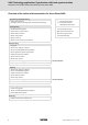
9400 Technology applications | Synchronism with mark synchronisation Overview of the technical documentation for Servo Drives 9400 Overview of the technical documentation for Servo Drives 9400 Project planning, selecting & ordering Legend: 9400 Hardware Manual Printed documentation Catalogue / electronic catalogue (DSC - Drive Solution Catalogue) Online documentation (PDF/Engineer online help) Mounting & wiring Abbreviations used: MA 9400 StateLine/HighLine BA Operating Instructions M
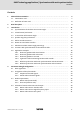
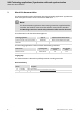
9400 Technology applications | Synchronism with mark synchronisation Contents Contents 1 About this documentation . . . . . . . . . . . . . . . . . . . . . . . . . . . . . . . . . . . . . . . . . . . . . . . . . . . . . . . . . 6 1.1 Conventions used . . . . . . . . . . . . . . . . . . . . . . . . . . . . . . . . . . . . . . . . . . . . . . . . . . . . . . . . . . . . . . . 7 1.2 Definition of notes used . . . . . . . . . . . . . . . . . . . . . . . . . . . . . . . . . . . . . . . . . . . . . . . .
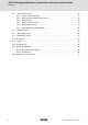
9400 Technology applications | Synchronism with mark synchronisation Contents 4 4.5 "Synchronism" mode" . . . . . . . . . . . . . . . . . . . . . . . . . . . . . . . . . . . . . . . . . . . . . . . . . . . . . . . . . . . 4.5.1 Master value processing . . . . . . . . . . . . . . . . . . . . . . . . . . . . . . . . . . . . . . . . . . . . . . . . . 4.5.2 Mark synchronisation (master value) . . . . . . . . . . . . . . . . . . . . . . . . . . . . . . . . . . . . . 4.5.3 Virtual clutch . . . . . . . . . . .
9400 Technology applications | Synchronism with mark synchronisation Contents 4.14 Parameterisable function blocks . . . . . . . . . . . . . . . . . . . . . . . . . . . . . . . . . . . . . . . . . . . . . . . . . 4.14.1 ApplicationError . . . . . . . . . . . . . . . . . . . . . . . . . . . . . . . . . . . . . . . . . . . . . . . . . . . . . . . . . 4.14.2 ClutchElectricalShaft. . . . . . . . . . . . . . . . . . . . . . . . . . . . . . . . . . . . . . . . . . . . . . . . . . . . . 4.14.
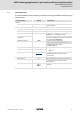
9400 Technology applications | Synchronism with mark synchronisation About this documentation 1 About this documentation This documentation contains information about the technology application "Synchronism with mark synchronisation" for the Servo Drives 9400 series. Note! This documentation supplements the mounting instructions supplied with the controller, the hardware manual and the software manual for the controller.
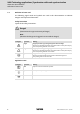
9400 Technology applications | Synchronism with mark synchronisation About this documentation Conventions used 1.1 Conventions used This documentation uses the following conventions to distinguish between different types of information: Type of information Writing Examples/notes Numbers Decimal separator Point The decimal point is always used. Example: 1234.56 Text Program name »« Window pane Italics The Message window... / the Options dialog box... Control element Bold The OK button...
9400 Technology applications | Synchronism with mark synchronisation About this documentation Definition of notes used 1.
400 Technology applications | Synchronism with mark synchronisation Brief description 2 Brief description The technology application "Synchronism with register formation and mark synchronisation" serves to implement a high-precision angular synchronism between the drives in the system. r Thanks to a free adjustable position resolution of up to 24 bits per motor revolution a very good synchronism result is achieved so that applications with direct drive can be resolved with high precision.
9400 Technology applications | Synchronism with mark synchronisation Brief description Required license/delivery r License stage Motion Control HighLevel or higher required. r The technology application can be selected in the »Engineer« application catalog. 10 L EDS94TA10040xxxx EN 1.
9400 Technology applications | Synchronism with mark synchronisation Introduction Synchronisation of the drives via a master angle 3 Introduction The following subchapters provide information on the electrical shaft. 3.1 Synchronisation of the drives via a master angle By coupling the drives via a master angle the positions are firmly allocated to each other like a mechanical shaft.
9400 Technology applications | Synchronism with mark synchronisation Introduction Virtual master/real master 3.2 Virtual master/real master Virtual master Virtual master / Slave 1 X10: DFout i d r In an interconnection, a drive takes over the task of the (virtual) master and is the first slave drive at the same time. r The master value created in the TA by the "Virtual master" function is transmitted via a bus system or the digital frequency output to the other slave drives.
9400 Technology applications | Synchronism with mark synchronisation Introduction Transmission of the master angle 3.
9400 Technology applications | Synchronism with mark synchronisation Introduction Master or actual value transfer? Cascade structure Each drive obtains its own master value/master angle which is created or merely prepared through the upstream drive. 3.6 Master or actual value transfer? Master value transmission The master value transfer results in a much quieter machine running. The mark corrections, superimposed control functions and disturbances of the drive, however, do not affect the system.
9400 Technology applications | Synchronism with mark synchronisation Introduction Functions with synchronisation via the electrical shaft 3.
9400 Technology applications | Synchronism with mark synchronisation Introduction Application examples 3.9 Application examples 3.9.1 Electronic gearbox with virtual master System bus Master/Slave i1 d1 v R1 Slave i2 d2 v R2 v n Virtual master (and slave 1) o Slave 2 p Electrical shaft, implemented here via system bus (CAN). [3-3] 3.9.
9400 Technology applications | Synchronism with mark synchronisation Introduction Application examples 3.9.3 Electronic gearbox as cascade The technology application "Electronic gearbox" is often operated as cascade since changes of speed/gearbox ratio of an upstream drive also have an effect on the subsequent drive. r Typical applications are, for instance, stretching machines, wire drawing machines and roller mills. r There is no position reference between tool and material.
9400 Technology applications | Synchronism with mark synchronisation Introduction Application examples 3.9.4 Tighten the web via trimming function with cascade In case a clearance has developed, the web must be "tightened" again. Only then the machine can be accelerated again via the master. The subsequent slave (cascade structure) must run along in the set ratio. Thus, the trimming function acts directly before or after the stretching factor.
9400 Technology applications | Synchronism with mark synchronisation Introduction Application examples 3.9.5 Relative synchronism with mark synchronisation and virtual master System bus Master/Slave Slave i1 d1 i2 v R1 Slave d2 a2 i3 v R2 d3 a3 v R3 v n Virtual master (and slave 1) o Slave 2 p Slave 3 q Electrical shaft, implemented here via system bus (CAN).
9400 Technology applications | Synchronism with mark synchronisation Introduction Application examples 3.9.6 Relative synchronism with mark synchronisation and real master System bus Master/Slave i1 d1 v R1 i2 d2 Slave i3 v R2 a2 d3 a3 v R3 v n Real master/slave 1 (digital frequency extension module required) o Slave 2 p Electrical shaft, implemented here via system bus (CAN).
9400 Technology applications | Synchronism with mark synchronisation Parameter setting & configuration 4 Parameter setting & configuration Note! The electrical shaft can be implemented with a bus system such as system bus (CAN) or Ethernet Powerlink or via digital frequency transmission. With regard to the configuration of the digital frequency extension module in the controller, two variants of technology applications are available in the »Engineer« application catalog.
9400 Technology applications | Synchronism with mark synchronisation Parameter setting & configuration Basic signal flow 4.
9400 Technology applications | Synchronism with mark synchronisation Parameter setting & configuration Assignment of the I/O terminals 4.2 Assignment of the I/O terminals 4.2.1 Setpoint and control signals The following tables contain the Lenze assignment of the analog and digital inputs for the "Synchronism" technology application.
9400 Technology applications | Synchronism with mark synchronisation Parameter setting & configuration Assignment of the I/O terminals 4.2.2 Actual value and status signals The following tables contain the Lenze assignment of the analog and digital outputs for the "Synchronism" technology application. r The default signal configuration if required can be easily changed by parameterising the multiplexer parameters assigned.
9400 Technology applications | Synchronism with mark synchronisation Parameter setting & configuration Machine parameters 4.
9400 Technology applications | Synchronism with mark synchronisation Parameter setting & configuration Machine parameters 4.3.1 Master axis (master shaft) For scaling and imaging the master value in the application, the machine parameters of the higher-level drive (master shaft) must be set. Note! When setting (scaling) the electrical shaft, ensure that the ratio and encoder constants are identical for all drives in the system. The reference to the scaling of the master drive is sensible.
9400 Technology applications | Synchronism with mark synchronisation Parameter setting & configuration Machine parameters O Tip! Setting the cycle (C03938) only is required if the selection "Modulo" is set as traversing range (C02528). For operation with a virtual master the following setting of the gearbox ratio is recommended to achieve a good resolution of the guiding angle/master value: • Numerator (C03930) = 100 • Denominator (C03931) = 1 4.3.
9400 Technology applications | Synchronism with mark synchronisation Parameter setting & configuration Machine parameters Example of determining the machine parameters for the slave axis 1. Set gearbox ratio for the motor in the form of a quotient (numerator and denominator): i2 = 12.612 = 12612/ 1000 – Numerator (C02520) = 12612 – Denominator (C02521) = 1000 i2 = 12.612 d2 = 200 mm 2. Set the same gearbox ratio for the position encoder: – Numerator (C02522) = 12612 – Denominator (C02523) = 1000 3.
9400 Technology applications | Synchronism with mark synchronisation Parameter setting & configuration Selection of master value source and output 4.
9400 Technology applications | Synchronism with mark synchronisation Parameter setting & configuration Selection of master value source and output 4.4.1 Master value source: Virtual master If the "Virtual master" is selected as master value source, the master value is created in the TA and transmitted via a bus system or the digital frequency output to the other slave drives.
9400 Technology applications | Synchronism with mark synchronisation Parameter setting & configuration Selection of master value source and output 4.4.2 Master value source: Digital frequency input To use the digital frequency input as master value source, the controller must be provided with digital frequency extension module (E94AYFLF). To ensure the integration of the extension module in the application, the TA "Synchronism with mark synchronisation" must be used as technology application.
9400 Technology applications | Synchronism with mark synchronisation Parameter setting & configuration "Synchronism" mode" 4.5 "Synchronism" mode" In the "Synchronism" (C03006 = "0") operating mode the drive follows the master value of the electrical shaft if the clutch is engaged.
9400 Technology applications | Synchronism with mark synchronisation Parameter setting & configuration "Synchronism" mode" 4.5.
9400 Technology applications | Synchronism with mark synchronisation Parameter setting & configuration "Synchronism" mode" 4.5.2 Mark synchronisation (master value) Real master/ Virtual master Dj C03006 = 0 v t Dj Dj TP TP M Slave v n Master value oMaster value with stretch factor [4-6] "Mark synchronisation" function in signal flow (schematic diagram) This function serves to carry out a mark synchronisation of the master value via touch probe sensor.
9400 Technology applications | Synchronism with mark synchronisation Parameter setting & configuration "Synchronism" mode" TP profile parameters r Parameter setting: Tab Application parameters dialog level Overview TP profile parameters Parameter Lenze setting Value Unit C03620 Positioning mode 0 C03621 Deactivation mode 0 C03623/1 Positive speed 3600.0000 unit/t C03623/2 Negative speed 3600.0000 unit/t C03626/1 Acceleration ramp 1.000 s C03626/2 Deceleration ramp 1.
9400 Technology applications | Synchronism with mark synchronisation Parameter setting & configuration "Synchronism" mode" 4.5.
9400 Technology applications | Synchronism with mark synchronisation Parameter setting & configuration "Synchronism" mode" 4.5.4 Master value trimming Real master/ Virtual master Dj C03006 = 0 v M t Dj Dj TP TP Slave v n Master value with clutch o Master value with trimming [4-8] "Master value trimming" function in the signal flow (schematic diagram) This function serves to adjust the master value.
9400 Technology applications | Synchronism with mark synchronisation Parameter setting & configuration "Synchronism" mode" 4.5.5 Setpoint processing Real master/ Virtual master Dj C03006 = 0 v t Dj Dj TP TP M Slave v n Master value with trimming o Actual value [4-9] "Setpoint processing" function in the signal flow (schematic diagram) This function is used for position ratio between the master shaft and the machine axis.
9400 Technology applications | Synchronism with mark synchronisation Parameter setting & configuration "Synchronism" mode" 4.5.6 Mark synchronisation (setpoint) Real master/ Virtual master Dj C03006 = 0 v t Dj Dj TP TP M Slave v n Master value with trimming o Actual value [4-10] "Mark synchronisation" function in signal flow (schematic diagram) This function serves to carry out a mark synchronisation of the setpoint via touch probe sensor.
9400 Technology applications | Synchronism with mark synchronisation Parameter setting & configuration "Synchronism" mode" TP profile parameters r Parameter setting: Tab Application parameters dialog level Overview Synchronism TP profile parameters Parameter Lenze setting Value Unit C03855 Positioning mode 0 C03856 Deactivation mode 0 C03858/1 Positive speed 1000.0000 unit/t C03858/2 Negative speed 1000.0000 unit/t C03861/1 Acceleration ramp 1.000 s C03861/2 Deceleration ramp 1.
9400 Technology applications | Synchronism with mark synchronisation Parameter setting & configuration "Homing" mode 4.
9400 Technology applications | Synchronism with mark synchronisation Parameter setting & configuration "Manual jog" mode 4.
9400 Technology applications | Synchronism with mark synchronisation Parameter setting & configuration "Positioning" mode" 4.
9400 Technology applications | Synchronism with mark synchronisation Parameter setting & configuration "Positioning" mode" Profile data record management For the profile data record management the FB L_PosProfileTable is used. This FB serves to file and manage up to four (travel) profiles and to "teach" target positions. r A profile describes a motion request which can be implemented by the SB LS_Positioner into a rotary motion.
9400 Technology applications | Synchronism with mark synchronisation Parameter setting & configuration Quick stop 4.9 Quick stop v M t t Slave LS_Quickstop n If the quick stop function is deactivated, the drive is led to the selected setpoint again via the set acceleration time. LS_Limiter n STOP t The basic function "Quick stop" brakes the drive to standstill within the deceleration time set for the quick stop function after a corresponding request independent of the setpoint selection.
9400 Technology applications | Synchronism with mark synchronisation Parameter setting & configuration Limiter 4.10 Limiter v M t t Slave LS_Quickstop n The basic function "Limiter" monitors the travel range limits via limit switches and parameterised software limit positions and can lead the drive to defined limit ranges when being asked accordingly by the safety module.
9400 Technology applications | Synchronism with mark synchronisation Parameter setting & configuration Limiter Control inputs of the function Lenze setting Signal configuration Control input (Multiplexer parameters) FALSE Positive limit switch C03150/1 FALSE Negative limit switch C03150/2 EDS94TA10040xxxx EN 1.
9400 Technology applications | Synchronism with mark synchronisation Parameter setting & configuration Brake control 4.11 Brake control The basic function "Brake control" serves to the wear free control and monitoring of a holding brake. LS_Brake In the simplest case, an optionally available brake module is used. M Alternatively the holding brake can also be controlled and monitored via the digital inputs/outputs.
9400 Technology applications | Synchronism with mark synchronisation Parameter setting & configuration Brake control Control/setpoint inputs of the function Lenze setting Signal configuration Control/setpoint input (Multiplexer parameters) FALSE Release brake C03165/1 FALSE Activate starting torque 2 C03165/2 FALSE Keep open brake at standstill C03165/3 FALSE Brake status signal C03165/4 FALSE Activate brake test C03165/5 FALSE Grind brake C03165/6 0 % Additional torque EDS9
9400 Technology applications | Synchronism with mark synchronisation Parameter setting & configuration Signal configuration 4.12 Signal configuration 4.12.1 Drive and motor interface If required, the preset signal configuration of the control and setpoint inputs of the drive and motor interface can be easily reconfigured per parameter setting of the assigned multiplexer parameters.
9400 Technology applications | Synchronism with mark synchronisation Parameter setting & configuration Signal configuration 4.12.2 Output ports If required, the preset signal configuration of the output ports can be easily reconfigured per parameter setting of the assigned multiplexer parameters. Output port "LPortAxisOut1" The output port LPortAxisOut1 is intended for the connection with a following axis.
9400 Technology applications | Synchronism with mark synchronisation Parameter setting & configuration Signal configuration Output port "LPortStatus1" The output port LPortStatus1 is intended for the connection with a higher-level control.
9400 Technology applications | Synchronism with mark synchronisation Parameter setting & configuration Application error messages 4.13 Application error messages For the output of application-specific error messages, an FB instance ApplicationError of the function block L_DevApplErr is available. r Via the 8 boolean inputs up to 8 different application error messages with parameterisable module ID, error ID and error response can be activated by the application.
9400 Technology applications | Synchronism with mark synchronisation Parameter setting & configuration Parameterisable function blocks 4.14 Parameterisable function blocks This subchapter lists all relevant parameterisable function blocks of the technology application and the corresponding parameters in alphabetical order. 4.14.1 ApplicationError Is an instance of Function L_DevApplErr Error handling Application error messages (C 53) Parameter Possible settings C05900 980 C05901/1...
9400 Technology applications | Synchronism with mark synchronisation Parameter setting & configuration Parameterisable function blocks 4.14.2 ClutchElectricalShaft Is an instance of Function L_LdClutchAxisP Time-controlled virtual clutch with position reference Virtual clutch (C 36) Parameter Possible settings C03665/1 0.010 s 130.000 Clutch in ramp • Acceleration ramp for synchronising to the master shaft. • Initialisation: 1.000 s C03665/2 0.010 s 130.
9400 Technology applications | Synchronism with mark synchronisation Parameter setting & configuration Parameterisable function blocks 4.14.3 4.14.4 ClutchStopPosition Is an instance of Function L_SdSetPosition Conversion of the set position after decoupling selected in the real units of the machine via C03679 into a position in [increments]. Virtual clutch (C 36) Parameter Possible settings C03679 -214000.0000 C03680 String of digits C03681 -2147483647 Information unit 214000.
9400 Technology applications | Synchronism with mark synchronisation Parameter setting & configuration Parameterisable function blocks 4.14.5 CompareTPDiffTool Is an instance of Function L_TbCompare Mark synchronisation (setpoint): Comparison of the determined TP difference and the TP limit parameterised in C03851 for the status message "TP limit exceeded" via C03875.
9400 Technology applications | Synchronism with mark synchronisation Parameter setting & configuration Parameterisable function blocks 4.14.7 Parameter Possible settings Information C03721 -214748.3647 unit/t 214748.3647 Speed X at the output • Read only • Is generated from the speed signal dnXSpeedOut_s. C03722 -214748.3647 unit/t 214748.3647 Speed Y at the output • Read only • Is generated from the speed signal dnYSpeedOut_s. C03723 -214748.3647 unit C03724 -214748.3647 214748.
9400 Technology applications | Synchronism with mark synchronisation Parameter setting & configuration Parameterisable function blocks 4.14.8 ElectricalShaftData Is an instance of Function L_SdSetAxisData Mapping of the machine parameters of the higher-level drive (master shaft). Master axis (master shaft) (C 26) Parameter Possible settings C03930 1 2147483647 Gearbox ratio - numerator • Initialisation: 1 C03931 1 2147483647 Gearbox ratio - denominator • Initialisation: 1 C03932 0.
9400 Technology applications | Synchronism with mark synchronisation Parameter setting & configuration Parameterisable function blocks 4.14.9 ElectricalShaftVal Is an instance of Function L_SdSetAxisVelocity Master value processing (C 33) Parameter Possible settings C03590 -214748.3647 C03591/1 String of digits Position unit • Read only C03591/2 String of digits Speed unit • Read only C03592 -214748.3647 unit/t 214748.
9400 Technology applications | Synchronism with mark synchronisation Parameter setting & configuration Parameterisable function blocks 4.14.10 4.14.11 4.14.12 FollowErrorHysteresis Is an instance of Function L_SdSetPosition Following error monitoring: Conversion of the following error hysteresis selected in the real units of the machine via C03916 into a position in [increments]. Parameter Possible settings C03916 -214000.
9400 Technology applications | Synchronism with mark synchronisation Parameter setting & configuration Parameterisable function blocks 4.14.13 4.14.14 62 HystTPDiffShaft Is an instance of Function L_SdSetPosition Mark synchronisation (master value): Conversion of the TP hysteresis selected in the real units of the machine via C03656 into a position in [increments]. Mark synchronisation (master value) (C 34) Parameter Possible settings C03656 -214000.
9400 Technology applications | Synchronism with mark synchronisation Parameter setting & configuration Parameterisable function blocks 4.14.15 4.14.16 LimitTPDiffShaft Is an instance of Function L_SdSetPosition Mark synchronisation (master value): Conversion of the TP limit selected in the real units of the machine via C03651 into a position in [increments]. Mark synchronisation (master value) (C 34) Parameter Possible settings C03651 -214000.
9400 Technology applications | Synchronism with mark synchronisation Parameter setting & configuration Parameterisable function blocks 4.14.17 MarkSynchronizationShaft Is an instance of Function L_LdPosCtrlLin Time-controlled profile generation with linear acceleration/deceleration ramps for mark synchronisation (master value).
9400 Technology applications | Synchronism with mark synchronisation Parameter setting & configuration Parameterisable function blocks Parameter Possible settings Information C3621 Deactivation mode 0 Positioning function deactivated: Lenze setting • The position output dnPosOut_p is set to 0. • The status signal bInTarget is reset to FALSE. 1 Positioning function changes to the stand-by state: • The position output dnPosOut_p is held on the current position dnActPos_p.
9400 Technology applications | Synchronism with mark synchronisation Parameter setting & configuration Parameterisable function blocks Parameter Possible settings C03639 0 Set position not yet reached. 1 Set position reached. 66 L Information Set position reached • Display of output signal bInTarget. EDS94TA10040xxxx EN 1.
9400 Technology applications | Synchronism with mark synchronisation Parameter setting & configuration Parameterisable function blocks 4.14.18 MarkSynchronizationTool Is an instance of Function L_LdPosCtrlLin Time-controlled profile generation with linear acceleration/deceleration ramps for mark synchronisation (setpoint).
9400 Technology applications | Synchronism with mark synchronisation Parameter setting & configuration Parameterisable function blocks Parameter Possible settings Information C3856 Deactivation mode 0 Positioning function deactivated: Lenze setting • The position output dnPosOut_p is set to 0. • The status signal bInTarget is reset to FALSE. 1 Positioning function changes to the stand-by state: • The position output dnPosOut_p is held on the current position dnActPos_p.
9400 Technology applications | Synchronism with mark synchronisation Parameter setting & configuration Parameterisable function blocks Parameter Possible settings Information C03874 0 Set position not yet reached. 1 Set position reached. 4.14.19 Set position reached • Display of output signal bInTarget. MonitFollowError Is an instance of Function L_LdMonitFollowError Following error monitoring Parameter Possible settings C03960 -214748.3647 C03961 String of digits Information unit 214748.
9400 Technology applications | Synchronism with mark synchronisation Parameter setting & configuration Parameterisable function blocks Parameter Possible settings Information C03559 Extrapolation cycles > selected value • Read only 0 No (OK) 1 Yes (error) 4.14.21 OverrideProfile Is an instance of Function L_PosProfileTable Storage and management of up to four travel profiles for the "positioning" mode. "Positioning" mode" (C 43) Parameter Possible settings Information C03970/1...
9400 Technology applications | Synchronism with mark synchronisation Parameter setting & configuration Parameterisable function blocks Parameter Possible settings Information C03977/1...4 Value is bit-coded: Touch probe configuration • The touch probe channels to be used are selected by setting the corresponding bits to "1". (subcode 1 ... 4 ≡ profile no. 1 ...
9400 Technology applications | Synchronism with mark synchronisation Parameter setting & configuration Parameterisable function blocks Parameter Possible settings Information C03983 DIS:bPosTeach • Display of input signal bPosTeach. 0 FALSE 1 TRUE C03984 0 Profile parameters are available. DIS:bBusy • Display of output signal bBusy. 1 Conversion active, no access to profile parameters at the moment. C03985 4.14.22 4.14.
9400 Technology applications | Synchronism with mark synchronisation Parameter setting & configuration Parameterisable function blocks Parameter Possible settings C03831 -2147483647 unit/t 2147483647 Speed at the input • Read only • Is generated from the speed signal dnSetSpeedIn_s. C03832 -2147483647 unit/t 2147483647 Speed at the output • Read only • Is generated from the speed signal dnSpeedOut_s. C03833 -214748.3647 unit 214748.
9400 Technology applications | Synchronism with mark synchronisation Parameter setting & configuration Parameterisable function blocks 4.14.24 4.14.25 74 TouchProbePositionShaft Is an instance of Function L_SdSetPosition Mark synchronisation (master value): Conversion of the TP position selected in the real units of the machine via C03612 into a position in [increments]. Mark synchronisation (master value) (C 34) Parameter Possible settings C03612 -214000.
9400 Technology applications | Synchronism with mark synchronisation Parameter setting & configuration Parameterisable function blocks 4.14.26 Trimming Is an instance of Function L_LdPosCtrlLin Master value trimming (C 37) Parameter Possible settings C03685 Information Positioning mode 0 Absolute positioning without limit stop: • When the positioning process is started (bExecute = TRUE), the outputs dnPosOut_p and dnSpeedOut_s are led to the target position using the set profile parameters.
9400 Technology applications | Synchronism with mark synchronisation Parameter setting & configuration Parameterisable function blocks Parameter Possible settings Information C3686 Deactivation mode 0 Positioning function deactivated: Lenze setting • The position output dnPosOut_p is set to 0. • The status signal bInTarget is reset to FALSE. 1 Positioning function changes to the stand-by state: • The position output dnPosOut_p is held on the current position dnActPos_p.
9400 Technology applications | Synchronism with mark synchronisation Parameter setting & configuration Parameterisable function blocks Parameter Possible settings Information C03704 0 Set position not yet reached. 1 Set position reached. 4.14.27 4.14.28 Set position reached • Display of output signal bInTarget. TrimmingOffsetAdjustment Is an instance of Function L_SdSetPosition Conversion of the offset position selected in the real units of the machine via C03676 into a position in [increments].
9400 Technology applications | Synchronism with mark synchronisation Parameter setting & configuration Parameterisable function blocks Parameter Possible settings Information C03570/1 0.010 s 130.000 Ramp for manual jog • Initialisation: 1.000 s C03570/2 0.010 s 130.000 Ramp for continuous operation/ single cycle • Initialisation: 1.000 s C03570/3 0.010 s 130.000 Stop ramp • Initialisation: 1.
)(('%$&. Your opinion is important to us These instructions were created to the best of our knowledge and belief to give you the best possible support for handling our product. If you have suggestions for improvement, please e-mail us to: feedback-docu@Lenze.de Thank you for your support.
© 10/2008 ) Lenze Automation GmbH Grünstraße 36 D-40667 Meerbusch Germany Service +49 (0)21 32 / 99 04-0 Lenze Service GmbH Breslauer Straße 3 D-32699 Extertal Germany 00 80 00 / 24 4 68 77 (24 h helpline) ¬ +49 (0)21 32 / 7 21 90 ¬ +49 (0)51 54 / 82-11 12 | Lenze@Lenze.de | Service@Lenze.de Þ www.Lenze.com EDS94TA10040xxxx 13277850 EN 1.