Ä.>
Lesen Sie zuerst diese Anleitung, bevor Sie mit den Arbeiten beginnen! Beachten Sie die enthaltenen Sicherheitshinweise. Please read these instructions before you start working! Follow the enclosed safety instructions. Veuillez lire attentivement cette documentation avant toute action ! Les consignes de sécurité doivent impérativement être respectées. Lea las instrucciones antes de empezar a trabajar. Observe las instrucciones de seguridad indicadas.
E94YCIB001B klappseite E94AYCIB
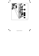
Legende zur Abbildung auf der Ausklappseite Pos. Beschreibung Ausführliche Information S205 DIP−Schalter zur Einstellung der l Anzahl von Prozessdatenwörtern und Parameterdatenwörtern l Übertragungsrate 22 X205 Anschluss für Spannungsversorgung l 2−polige Steckerleiste mit Federkraftanschluss 20 X206 INTERBUS−Anschluss, Eingang (IN) l 9−poliger Sub−D−Stecker X207 INTERBUS−Anschluss, Ausgang (OUT) l 9−polige Sub−D−Buchse 16 MS ME BS 27 LED−Statusanzeigen zur Diagnose BE DE 0Abb.
Inhalt i 1 Über diese Dokumentation . . . . . . . . . . . . . . . . . . . . . . . . . . . . . . . . . . . . . . . . . . Verwendete Konventionen . . . . . . . . . . . . . . . . . . . . . . . . . . . . . . . . . . . . . . . . . . Verwendete Hinweise . . . . . . . . . . . . . . . . . . . . . . . . . . . . . . . . . . . . . . . . . . . . . . . 2 Sicherheitshinweise . . . . . . . . . . . . . . . . . . . . . . . . . . . . . . . . . . . . . . . . . . . . . . . . 9 3 Produktbeschreibung . . . . . . . . . .
1 Über diese Dokumentation 1 Über diese Dokumentation Inhalt Diese Dokumentation enthält ... ƒ Informationen zur mechanischen und elektrischen Installation des Kommunikationsmoduls; ƒ Sicherheitshinweise, die Sie unbedingt beachten müssen; ƒ Angaben über Versionsstände der zu verwendenden Lenze Grundgeräte.
Über diese Dokumentation 1 Verwendete Konventionen Verwendete Konventionen Diese Dokumentation verwendet folgende Konventionen zur Unterscheidung verschiedener Arten von Information: Informationsart Auszeichnung Beispiele/Hinweise Zahlenschreibweise Dezimaltrennzeichen Punkt Es wird generell der Dezimalpunkt verwendet. Beispiel: 1234.56 Symbole Seitenverweis EDK94AYCIB DE/EN/FR/ES/IT 1.
1 Über diese Dokumentation Verwendete Hinweise Verwendete Hinweise Um auf Gefahren und wichtige Informationen hinzuweisen, werden in dieser Dokumentation folgende Piktogramme und Signalwörter verwendet: Sicherheitshinweise Aufbau der Sicherheitshinweise: Gefahr! (kennzeichnet die Art und die Schwere der Gefahr) Hinweistext (beschreibt die Gefahr und gibt Hinweise, wie sie vermieden werden kann) Piktogramm und Signalwort Bedeutung Gefahr! Gefahr von Personenschäden durch gefährliche elektrische Spa
Sicherheitshinweise 2 2 Sicherheitshinweise Gefahr! Unsachgemäßer Umgang mit dem Kommunikationsmodul und dem Grundgerät kann schwere Personenschäden und Sachschäden verursachen. Beachten Sie die in der Dokumentation zum Grundgerät enthaltenen Sicherheitshinweise und Restgefahren. Stop! Elektrostatische Entladung Durch elektrostatische Entladung können elektronische Bauteile innerhalb des Kommunikationsmoduls beschädigt oder zerstört werden. Mögliche Folgen: ƒ Das Kommunikationsmodul ist defekt.
3 Produktbeschreibung Funktion 3 Produktbeschreibung Funktion Das Kommunikationsmodul koppelt Lenze Servo Drives 9400 an das Kommunikationssystem INTERBUS. Bestimmungsgemäße Verwendung Das Kommunikationsmodul ... ƒ ist eine Zubehör−Baugruppe, die mit folgenden Lenze Grundgeräten eingesetzt werden kann: Produktreihe Typenbezeichnung ab Hardwarestand ab Softwarestand Servo Drives 9400 HighLine E94AxHxxxxx 1A 03.00 ƒ ist ein Betriebsmittel zum Einsatz in industriellen Starkstromanlagen.
Produktbeschreibung 3 Identifikation Identifikation E94YCIB005 E94 A Y C IB PA 01.00 Produktreihe Gerätegeneration Modulkennung: Erweiterungsmodul Modultyp: Kommunikationsmodul INTERBUS Hardwarestand Softwarestand EDK94AYCIB DE/EN/FR/ES/IT 1.
4 Technische Daten Allgemeine Daten 4 Technische Daten Allgemeine Daten Bereich Werte Bestell−Bezeichnung E94AYCIB Kommunikationsprofil INTERBUS Schnittstellen l l Eingang (IN): 9−poliger Sub−D−Stecker Ausgang (OUT): 9−polige Sub−D−Buchse Kommunikationsmedium RS485 Netzwerktopologie Ring INTERBUS−Teilnehmeranzahl l l 1 Master 512 Slaves Übertragungsrate 500 kBit/s oder 2 MBit/s (über DIP−Schalter oder Codestelle einstellbar) Max.
Technische Daten 4 Abmessungen Abmessungen E94YCXX005 a 89 mm b 134 mm b1 87 mm e 23 mm EDK94AYCIB DE/EN/FR/ES/IT 1.
5 5 Mechanische Installation Mechanische Installation Montage E94YCXX001G Demontage E94AYCXX001H 14 EDK94AYCIB DE/EN/FR/ES/IT 1.
Elektrische Installation 6 EMV−gerechte Verdrahtung 6 Elektrische Installation EMV−gerechte Verdrahtung In typischen Anlagen ist die standardmäßige Schirmung des INTERBUS−Kabels ausreichend. In sehr stark gestörten Umgebungen kann eine Verbesserung der EMV−Festigkeit durch eine zusätzliche Erdung des Kabelschirms ermöglicht werden. Beachten Sie dazu folgende Hinweise: 1. Der Abstand der zusätzlichen Erdung der INTERBUS−Stecker (Sub−D, 9−polig) ist abhängig vom Steckplatz des Moduls.
6 Elektrische Installation INTERBUS−Anschluss INTERBUS−Anschluss Der INTERBUS−Anschluss des Kommunikationsmoduls erfolgt über X206 (Eingang, 9−poliger Sub−D−Stecker) und X207 (Ausgang, 9−polige Sub−D−Buchse).
Elektrische Installation 6 INTERBUS−Anschluss Belegung der 9−poligen Sub−D−Buchse X207 (OUT) Pin Bezeichnung Ein−/Ausgang Beschreibung 1 DO2 Ausgang RS485: DO2 nicht invertiert 2 DI2 Eingang RS485: DI2 nicht invertiert 3 GND 4 GND 5 Vcc5 Ausgang 5 V DC 6 /DO2 Ausgang RS485: DO2 invertiert 7 /DI2 Eingang RS485: DI2 invertiert 8 Vcc5 Ausgang 5 V DC 9 RBST Melde−Eingang Verbindung zum abgehenden INTERBUS gesteckt. EDK94AYCIB DE/EN/FR/ES/IT 1.
6 Elektrische Installation Abmessungen 9−polige Sub−D−Steckverbinder Abmessungen 9−polige Sub−D−Steckverbinder Hinweis! Halten Sie die Abmessungen der 9−poligen Sub−D−Steckverbinder für die INTERBUS−Anschlüsse X206/X207 ein. E94YCIB001G 18 EDK94AYCIB DE/EN/FR/ES/IT 1.
Elektrische Installation 6 Kabelspezifikation Kabelspezifikation Allgemeine Eigenschaften Kabeltyp Meterware, (z. B. PHOENIX CONTACT: IBS RBC Meter−T, Best.−Nr. 28 06 28 6) Leiteranzahl 3 × 2, paarig verseilt, mit gemeinsamer Abschirmung Leiterquerschnitt > 0.
6 Elektrische Installation Externe Spannungsversorgung Externe Spannungsversorgung Das Kommunikationsmodul kann extern über separate Versorgungsleitungen an der 2−poligen Steckerleiste (X205) mit Spannung versorgt werden. Hinweis! Verwenden Sie bei externer Spannungsversorgung und bei größeren Entfernungen zwischen den Schaltschränken in jedem Schaltschrank immer ein separates und nach EN 61800−5−1 sicher getrenntes Netzteil ("SELV"/"PELV").
Inbetriebnahme 7 Vor dem ersten Einschalten 7 Inbetriebnahme Vor dem ersten Einschalten Stop! Bevor Sie das Grundgerät mit dem Kommunikationsmodul erstmalig einschalten, überprüfen Sie die gesamte Verdrahtung auf Vollständigkeit, Kurzschluss und Erdschluss. EDK94AYCIB DE/EN/FR/ES/IT 1.
7 Inbetriebnahme Einstellmöglichkeiten durch DIP−Schalter Einstellmöglichkeiten durch DIP−Schalter E94YCIB001D Über den DIP−Schalter (S205) können eingestellt werden: ƒ Anzahl der Prozessdatenwörter (PD) mit Schalter 1 ... 4 ƒ Anzahl der Parameterdatenwörter (PCP) mit Schalter 5 und 6 ƒ Übertragungsrate mit Schalter 8 Lenze−Einstellung: alle Schalter "OFF" DIP−Schalter 7 hat keine Funktion. 22 EDK94AYCIB DE/EN/FR/ES/IT 1.
Inbetriebnahme 7 Einstellmöglichkeiten durch DIP−Schalter Hinweis! Um geänderte Einstellungen zu aktivieren, schalten Sie die Spannungsversorgung des Kommunikationsmoduls aus und anschließend wieder ein. Die Einstellungen können Sie auch über Codestellen vornehmen: ƒ Alle DIP−Schalter = "OFF" (Lenze−Einstellung): Beim Einschalten wird die Konfiguration aus den Codestellen C13892/C14892, C13893/C14893 und C13894/C14894 aktiv.
7 Inbetriebnahme Einstellmöglichkeiten durch DIP−Schalter Anzahl der Prozessdatenwörter (PD) einstellen ƒ Die Anzahl der Prozessdatenwörter können Sie über die Schalter 1 ... 4 oder die Codestelle C13893 / C14893 einstellen. ƒ 0 ... 10 Prozessdatenwörter können verwendet werden. ƒ Die aktuelle Einstellung wird in C13860/2 / C14860/2 angezeigt. Hinweis! Die Datenwortsumme (PD + PCP) muss 1 ... 10 Wörter betragen. Unzulässige Einstellungen werden durch die LED "BE" (blinkt rot, 27) signalisiert.
Inbetriebnahme 7 Einstellmöglichkeiten durch DIP−Schalter Anzahl der Parameterdatenwörter (PCP) einstellen ƒ Die Anzahl der Parameterdatenwörter können Sie über die Schalter 5 und 6 oder die Codestelle C13892 / C14892 einstellen. ƒ 0, 1, 2 oder 4 Parameterdatenwörter können verwendet werden. ƒ Die aktuelle Einstellung wird in C13860/1 / C14860/1 angezeigt. Hinweis! Die Datenwortsumme (PD + PCP) muss 1 ... 10 Wörter betragen.
7 Inbetriebnahme Einstellmöglichkeiten durch DIP−Schalter Übertragungsrate einstellen ƒ Die Übertragungsrate können Sie über den Schalter 8 oder die Codestelle C13894 / C14894 einstellen. ƒ Die aktuelle Einstellung der Übertragungsrate wird in C13863 / C14863 angezeigt. DIP−Schalter OFF 1 2 3 4 5 6 7 8 26 Schalter 8 Übertragungsrate Maximale Leitungslänge zwischen benachbarten Teilnehmern OFF 500 kBit/s 400 m ON 2 MBit/s 150 m ON EDK94AYCIB DE/EN/FR/ES/IT 1.
Diagnose 8 LED−Statusanzeigen 8 Diagnose LED−Statusanzeigen E94YCIB001F LED Pos. Farbe Zustand MS grün blinkt MS grün an Das Kommunikationsmodul ist mit Spannung versorgt und hat eine Verbindung zum Grundgerät. ME rot an Es liegt ein Fehler im Bereich des Kommunikationsmoduls vor. BS grün aus Das Kommunikationsmodul ist am Feldbus nicht aktiv. Datenzyklen werden nicht ausgeführt. blinkt Die Kommunikation über das Kommunikationsmodul ist aufgebaut. Der INTERBUS ist aktiv.
Legend for fold−out page Pos. Description Detailed information S205 DIP switch for setting the l number of process data words and parameter data words l Baud rate 46 X205 Connection for voltage supply l 2−pin plug connector with spring connection 44 X206 INTERBUS connection, input (IN) l 9−pin Sub−D connector X207 INTERBUS connection, output (OUT) l 9−pin Sub−D socket 40 MS ME BS LED status indicators for diagnostics 51 BE DE 0Fig. 0Tab. 0 28 EDK94AYCIB DE/EN/FR/ES/IT 1.
Contents i 1 About this documentation . . . . . . . . . . . . . . . . . . . . . . . . . . . . . . . . . . . . . . . . . . . Conventions used . . . . . . . . . . . . . . . . . . . . . . . . . . . . . . . . . . . . . . . . . . . . . . . . . . Notes used . . . . . . . . . . . . . . . . . . . . . . . . . . . . . . . . . . . . . . . . . . . . . . . . . . . . . . . . 30 31 32 2 Safety instructions . . . . . . . . . . . . . . . . . . . . . . . . . . . . . . . . . . . . . . . . . . . . . . . . .
1 About this documentation 1 About this documentation Contents This documentation contains ... ƒ information about the mechanical and electrical installation of the communication module; ƒ safety instructions which must be followed; ƒ specifications for the versions of the Lenze standard devices to be used.
About this documentation 1 Conventions used Conventions used This documentation uses the following conventions to distinguish between different types of information: Type of information Identification Examples/notes Numbers Decimal separator Point The decimal point is used throughout this documentation. Example: 1234.56 Symbols Page reference EDK94AYCIB DE/EN/FR/ES/IT 1.
1 About this documentation Notes used Notes used The following pictographs and signal words are used in this documentation to indicate dangers and important information: Safety instructions Structure of safety instructions: Danger! (characterises the type and severity of danger) Note (describes the danger and gives information about how to prevent dangerous situations) Pictograph and signal word Meaning Danger! Danger of personal injury through dangerous electrical voltage.
Safety instructions 2 2 Safety instructions Danger! Inappropriate handling of the communication module and the standard device can cause serious personal injury and material damage. Observe the safety instructions and residual hazards described in the documentation for the standard device. Stop! Electrostatic discharge Electronic components of the communication module can be damaged or destroyed through electrostatic discharge. Possible consequences: ƒ The communication module is damaged.
3 Product description Function 3 Product description Function The communication module connects Lenze Servo Drives 9400 to the INTERBUS communication system. Application as directed The communication module ... ƒ is an accessory which can be used in conjunction with the following Lenze standard devices: Product series Type designation from hardware version from software version Servo Drives 9400 HighLine E94AxHxxxxx 1A 03.00 ƒ is intended for use in industrial power systems.
Product description 3 Identification Identification E94YCIB005 E94 A Y C IB PA 01.00 Product series Version Module code: extension module Module type: communication module INTERBUS Hardware version Software version EDK94AYCIB DE/EN/FR/ES/IT 1.
4 Technical data General Data 4 Technical data General Data Range Values Order designation E94AYCIB Communication profile INTERBUS Interfaces l l Input (IN): 9−pin Sub−D connector Input (OUT): 9−pin Sub−D socket Communication medium RS485 Network topology Ring Number of INTERBUS nodes l l 1 master 512 slaves Baud rate 500 kBit/s or 2 MBit/s (adjustable by means of DIP switches or codes) Max.
Technical data 4 Dimensions Dimensions E94YCXX005 a 89 mm b 134 mm b1 87 mm e 23 mm EDK94AYCIB DE/EN/FR/ES/IT 1.
5 5 Mechanical installation Mechanical installation Mounting E94YCXX001G Dismounting E94AYCXX001H 38 EDK94AYCIB DE/EN/FR/ES/IT 1.
Electrical installation 6 Wiring according to EMC 6 Electrical installation Wiring according to EMC In typical installations, the standard shielding of the INTERBUS cable is sufficient. In environments that are subject to severe interference, electromagnetic compatibility can be improved by means of an additional PE connection for the cable shield. Please observe the following instructions: 1.
6 Electrical installation INTERBUS connection INTERBUS connection The INTERBUS is connected to the communication module by means of X206 (input, 9−pin Sub−D connector) and X207 (output, 9−pin Sub−D socket).
Electrical installation 6 INTERBUS connection Assignment of the 9−pin Sub−D socket X207 (OUT) Pin Designation Input/Output Description 1 DO2 Output RS485: DO2 not inverted 2 DI2 Input RS485: DI2 not inverted 3 GND 4 GND 5 Vcc5 Output 5 V DC 6 /DO2 Output RS485: DO2 inverted 7 /DI2 Input RS485: DI2 inverted 8 Vcc5 Output 5 V DC 9 RBST Signal input Connection to outgoing INTERBUS plugged in. EDK94AYCIB DE/EN/FR/ES/IT 1.
6 Electrical installation Dimensions 9−pin Sub−D connector Dimensions 9−pin Sub−D connector Note! Adhere to the dimensions of the 9−pin Sub−D connector for the INTERBUS ports X206/X207. E94YCIB001G 42 EDK94AYCIB DE/EN/FR/ES/IT 1.
Electrical installation 6 Cable specification Cable specification General characteristics Cable type Sold by the meter, (e.g. PHOENIX CONTACT: IBS RBC Meter−T, Order No. 28 06 28 6) Number of conductors 3 × 2, twisted pairs, with shared shield Conductor cross−section > 0.
6 Electrical installation External voltage supply External voltage supply The communication module can be supplied with voltage via separate supply leads connected to the 2−pin plug connector (X205). Note! Always use a separate power supply unit in every control cabinet and safely separate it according to EN 61800−5−1 ("SELV"/"PELV") in case of external voltage supply and larger distances between the control cabinets.
Commissioning 7 Before switching on 7 Commissioning Before switching on Stop! Before switching on the standard device with the communication module for the first time, check the entire wiring for completeness, short circuit and earth fault. EDK94AYCIB DE/EN/FR/ES/IT 1.
7 Commissioning DIP switch settings DIP switch settings E94YCIB001D The DIP switches (S205) can be used for adjustment purposes: ƒ Number of process data words (PD) with switches 1 to 4 ƒ Number of parameter data words (PCP)with switches 5 and 6 ƒ Baud rate with switch 8 Lenze setting: all switches "OFF" DIP switch 7 does not perform any function. 46 EDK94AYCIB DE/EN/FR/ES/IT 1.
Commissioning 7 DIP switch settings Note! Switch off the voltage supply of the communication module and then on again in order to activate changed settings. You can also carry out the settings by means of codes: ƒ All DIP switches = "OFF" (Lenze setting): When you switch the power on, the configuration determined by the codes C13892/C14892, C13893/C14893 and C13894/C14894 becomes active.
7 Commissioning DIP switch settings Setting the number of process data words (PD) ƒ You can use switches 1 to 4 or the code C13893 / C14893 to set the number of process data words. ƒ 0 to 10 process data words can be used. ƒ The current setting is shown in C13860/2 / C14860/2. Note! The total number of data words (PD + PCP) must be between 1 and 10. Impermissible settings are signalled by the "BE" LED (flashes 51) red.
Commissioning 7 DIP switch settings Setting the number of parameter data words (PCP) ƒ You can use switches 5 and 6 or the code C13892 / C14892 to set the number of parameter data words. ƒ 0, 1, 2 or 4 parameter data words can be used. ƒ The current setting is shown in C13860/1 / C14860/1. Note! The total number of data words (PD + PCP) must be between 1 and 10. Impermissible settings are signalled by the "BE" LED (flashes 51) red).
7 Commissioning DIP switch settings Baud rate setting ƒ You can use switch 8 or the code C13894 / C14894 to set the baud rate. ƒ The current setting of the baud rate is shown in C13863 / C14863. DIP switch OFF 1 2 3 4 5 6 7 8 50 Switch 8 Baud rate Maximum cable length between neighbouring nodes OFF 500 kBit/s 400 m ON 2 Mbits/s 150 m ON EDK94AYCIB DE/EN/FR/ES/IT 1.
Diagnostics 8 LED status displays 8 Diagnostics LED status displays E94YCIB001F LED Pos. Colour Condition MS green flashes MS green on The communication module is being supplied with voltage and is connected to the standard device. ME red on There is a fault in the area of the communication module. BS green off The communication module is not active on the field bus. Data cycles are not being executed. flashes Communication via the communication module has been set up.
Légende de l’illustration de la page dépliante Pos.
Sommaire i 1 Présentation du document . . . . . . . . . . . . . . . . . . . . . . . . . . . . . . . . . . . . . . . . . . . Conventions utilisées . . . . . . . . . . . . . . . . . . . . . . . . . . . . . . . . . . . . . . . . . . . . . . . Consignes utilisées . . . . . . . . . . . . . . . . . . . . . . . . . . . . . . . . . . . . . . . . . . . . . . . . . 54 55 56 2 Consignes de sécurité . . . . . . . . . . . . . . . . . . . . . . . . . . . . . . . . . . . . . . . . . . . . . . .
1 Présentation du document 1 Présentation du document Contenu Ce document contient ... ƒ des informations sur l’installation mécanique et électrique du module de communication ; ƒ des consignes de sécurité qui doivent impérativement être respectées ; ƒ des indications sur les versions des appareils de base Lenze à utiliser.
Présentation du document 1 Conventions utilisées Conventions utilisées Pour faire la distinction entre différents types d’informations, ce document utilise les conventions suivantes : Type d’information Marquage Exemples/remarques Représentation des chiffres Séparateur décimal Point Le point décimal est généralement utilisé. Exemple : 1234.56 Renvoi à une autre page présentant des informations supplémentaires Exemple : 16 = voir page 16 Symboles Renvoi à une page EDK94AYCIB DE/EN/FR/ES/IT 1.
1 Présentation du document Consignes utilisées Consignes utilisées Pour indiquer des risques et des informations importantes, la présente documentation utilise les mots et symboles suivants : Consignes de sécurité Présentation des consignes de sécurité Danger ! (Le pictogramme indique le type de risque.) Explication (L’explication décrit le risque et les moyens de l’éviter.
Consignes de sécurité 2 2 Consignes de sécurité Danger ! Toute utilisation non conforme à la fonction du module de communication et de l’appareil de base risque d’entraîner des dommages corporels et matériels importants. Tenir compte des consignes de sécurité et des dangers résiduels indiqués dans la documentation de l’appareil de base.
3 Description du produit Fonction 3 Description du produit Fonction Le module de communication relie les Servo Drives 9400 de Lenze au système de communication INTERBUS. Utilisation conforme à la fonction Le module de communication ... ƒ est un accessoire compatible avec les appareils de base Lenze suivants : Série d’appareils Référence de commande A partir de la version matérielle A partir de la version logicielle Servo Drives 9400 HighLine E94AxHxxxxx 1A 03.
Description du produit 3 Identification Identification E94YCIB005 E94 A Y C IB PA 01.00 Série d’appareils Génération d’appareils Identification du module : module d’extension Type de module : module de communication INTERBUS Version matérielle Version logicielle EDK94AYCIB DE/EN/FR/ES/IT 1.
4 Spécifications techniques Caractéristiques générales 4 Spécifications techniques Caractéristiques générales Critère Valeurs Référence de commande E94AYCIB Profil de communication INTERBUS Interfaces l l Entrée (IN) : connecteur SUB−D mâle 9 broches Sortie (OUT) : connecteur SUB−D femelle 9 broches Support de communication RS485 Topologie du réseau Anneau Nombre de participants INTERBUS l Vitesse de transmission 500 kbits/s ou 2 Mbits/s (réglable via interrupteur DIP ou via code) Longu
Spécifications techniques 4 Encombrements Encombrements E94YCXX005 a 89 mm b 134 mm b1 87 mm e 23 mm EDK94AYCIB DE/EN/FR/ES/IT 1.
5 5 Installation mécanique Installation mécanique Montage E94YCXX001G Démontage E94AYCXX001H 62 EDK94AYCIB DE/EN/FR/ES/IT 1.
Installation électrique 6 Câblage conforme CEM 6 Installation électrique Câblage conforme CEM Généralement, un blindage standard du câble INTERBUS suffit. Dans les environnements soumis à de fortes perturbations, il est possible d’améliorer la résistance CEM par une mise à la terre supplémentaire du blindage du câble. Tenir compte des consignes suivantes : 1. L’écart entre la liaison à la terre et les connecteurs SUB−D 9 broches INTERBUS dépend de l’emplacement du module. Il est...
6 Installation électrique Raccordement INTERBUS Raccordement INTERBUS La raccordement du module de communication à l’INTERBUS s’effectue via les ports X206 (entrée, connecteur SUB−D mâle 9 broches) et X207 (sortie, connecteur SUB−D femelle 9 broches).
Installation électrique 6 Raccordement INTERBUS Affectation du connecteur Sub−D femelle 9 broches X207 (OUT) Broche Désignation Entrée/sortie Description 1 DO2 Sortie RS485 : DO2 non inversé 2 DI2 Entrée RS485 : DI2 non inversé 3 GND 4 GND 5 Vcc5 Sortie 5 V cc 6 /DO2 Sortie RS485 : DO2 inversé 7 /DI2 Entrée RS485 : DI2 inversé 8 Vcc5 Sortie 5 V cc 9 RBST Entrée de signalement Raccordement effectué avec l’Interbus entrant. EDK94AYCIB DE/EN/FR/ES/IT 1.
6 Installation électrique Encombrements des connecteurs Sub−D 9 broches Encombrements des connecteurs Sub−D 9 broches Remarque importante ! Respecter les cotes d’encombrement des connecteurs Sub−D 9 broches pour les raccordements INTERBUS X206/X207. E94YCIB001G 66 EDK94AYCIB DE/EN/FR/ES/IT 1.
Installation électrique 6 Spécifications du câble Spécifications du câble Caractéristiques générales Type de câble Au mètre, (ex. : PHOENIX CONTACT : IBS RBC Meter−T, réf. de commande 28 06 28 6) Nombre de conducteurs 3 × 2, torsadés par paire, avec blindage Section de câble > 0.
6 Installation électrique Alimentation externe Alimentation externe Le module de communication peut être alimenté par une source externe via des câbles distincts reliés au bornier enfichable X205. Remarque importante ! En cas d’alimentation externe et d’écarts importants entre les armoires de commande, utiliser impérativement dans chacune d’elles un bloc d’alimentation avec coupure de sécurité ("SELV"/"PELV") séparé et conforme à la norme EN 61800−5−1.
Mise en service 7 Avant la première mise sous tension 7 Mise en service Avant la première mise sous tension Stop ! Avant la première mise sous tension de l’appareil de base avec le module de communication, vérifier si le câblage a été correctement réalisé dans son intégralité et rechercher d’éventuels courts−circuits (à la terre). EDK94AYCIB DE/EN/FR/ES/IT 1.
7 Mise en service Réglages possibles par interrupteurs DIP Réglages possibles par interrupteurs DIP E94YCIB001D Réglages pouvant être effectués via les interrupteurs DIP (S205) : ƒ Nombre de mots de données process (PD) via interrupteurs 1 à 4 ƒ Nombre de mots de données paramètres (PCP) via interrupteurs 5 et 6 ƒ Vitesse de transmission via interrupteur 8 Réglage Lenze : tous les interrupteurs en position "OFF" Aucune fonction n’est affectée à l’interrupteur 7. 70 EDK94AYCIB DE/EN/FR/ES/IT 1.
Mise en service 7 Réglages possibles par interrupteurs DIP Remarque importante ! Pour activer un réglage modifié, couper brièvement l’alimentation du module de communication. Les réglages peuvent aussi être effectués en utilisant les codes : ƒ Tous les interrupteurs DIP sont en position "OFF" (réglage Lenze) : A la mise sous tension, c’est la configuration résultant des codes C13892/C14892, C13893/C14893 et C13894/C14894 qui est activée.
7 Mise en service Réglages possibles par interrupteurs DIP Réglage du nombre de mots de données process (PD) ƒ Le nombre de mots de données process peut être réglé à l’aide des interrupteurs 1 à 4 ou via le code C13893/C14893. ƒ Entre 0 et 10 mots de données process peuvent être utilisés. ƒ Le réglage actuel est indiqué en C13860/2/C14860/2. Remarque importante ! Le nombre total de mots de données (PD + PCP) doit être compris entre 1 et 10.
Mise en service 7 Réglages possibles par interrupteurs DIP Réglage du nombre de mots de données paramètres (PCP) ƒ Le nombre de mots de données paramètres peut être réglé à l’aide des interrupteurs 5 et 6 ou via le code C13892/C14892. ƒ 0, 1, 2 ou 4 mots de données paramètres sont admissibles. ƒ Le réglage actuel est indiqué en C13860/1/C14860/1. Remarque importante ! Le nombre total de mots de données (PD + PCP) doit être compris entre 1 et 10.
7 Mise en service Réglages possibles par interrupteurs DIP Réglage de la vitesse de transmission ƒ La vitesse de transmission peut être réglée via l’interrupteur 8 ou le code C13894/C14894. ƒ Le réglage actuel de la vitesse de transmission est affiché en C13863/C14863. Interrupteurs DIP OFF 1 2 3 4 5 6 7 8 74 Interrupteur 8 Vitesse de transmission Longueur de câble maximale entre participants voisins OFF 500 kbits/s 400 m ON 2 Mbits/s 150 m ON EDK94AYCIB DE/EN/FR/ES/IT 1.
Diagnostic 8 Affichage d’état par LED 8 Diagnostic Affichage d’état par LED E94YCIB001F LED Pos. Couleur Etat MS Vert Clignote MS Vert ON Le module de communication est sous tension et la liaison avec l’appareil de base est établie. ME Rouge ON Une erreur a été détectée au niveau du module de communication. BS Vert OFF Le module de communication n’est pas activé sur le bus de terrain ; cycles de données non exécutés. Clignote La communication via le module est en cours.
Leyenda de la ilustración del lado abatible Pos.
Contenido i 1 Acerca de esta documentación . . . . . . . . . . . . . . . . . . . . . . . . . . . . . . . . . . . . . . . . Convenciones utilizadas . . . . . . . . . . . . . . . . . . . . . . . . . . . . . . . . . . . . . . . . . . . . . Indicaciones utilizadas . . . . . . . . . . . . . . . . . . . . . . . . . . . . . . . . . . . . . . . . . . . . . . 78 79 80 2 Instrucciones de seguridad . . . . . . . . . . . . . . . . . . . . . . . . . . . . . . . . . . . . . . . . . . .
1 Acerca de esta documentación 1 Acerca de esta documentación Contenido Esta documentación contiene ... ƒ Información para la instalación mecánica y eléctrica del módulo de comunicaciones. ƒ Instrucciones de Seguridad, que deben ser aplicadas. ƒ Datos de las versiones de los equipos básicos Lenze a ser utilizados.
Acerca de esta documentación 1 Convenciones utilizadas Convenciones utilizadas Esta documentación utiliza las siguientes convenciones para distinguir diferentes tipos de información: Tipo de información Marcación Ejemplos/indicaciones Números Separador decimal Punto En general se usa el punto decimal. Ejemplo: 1234.56 Símbolos Referencia de página EDK94AYCIB DE/EN/FR/ES/IT 1.
1 Acerca de esta documentación Indicaciones utilizadas Indicaciones utilizadas Para indicar peligros e información importante, se utilizan en esta documentación los siguientes términos indicativos y símbolos: Instrucciones de seguridad Estructura de las instrucciones de seguridad: ¡Peligro! (indican el tipo y la gravedad del peligro) Texto indicativo (describe el peligro y da instrucciones para evitarlo) Pictograma y término indicativo Significado ¡Peligro! Riesgo de daños personales por voltaje e
Instrucciones de seguridad 2 2 Instruccionesde seguridad ¡Peligro! El uso inapropiado del módulo de comunicaciones y del equipo básico puede causar accidentes y daños materiales. Observe las Instrucciones de Seguridad y Riesgos Residuales contenidos en la documentación del equipo básico. ¡Alto! Descarga electrostática A causa de una descarga electrostática podrían resultar dañados o destruidos componentes electrónicos dentro del módulo de comunicaciones.
3 Descripción del producto Función 3 Descripción del producto Función El módulo de comunicaciones se acopla al Lenze Servo Drives 9400 con el sistema de comunicaciones INTERBUS. Uso previsto El módulo de comunicaciones ... ƒ es un accesorio que puede conectarse con el siguiente equipo básico Lenze: Serie Denominación de tipo A partir de la versión de A partir de la versión de hardware software Servo Drives 9400 HighLine E94AxHxxxxx 1A 03.
Descripción del producto 3 Identificación Identificación E94YCIB005 E94 A Y C IB PA 01.00 Serie de productos Generación de equipos Caracterización del módulo: módulo de ampliación Tipo de módulo: módulo de comunicación INTERBUS Versión de hardware Versión de software EDK94AYCIB DE/EN/FR/ES/IT 1.
4 Datos técnicos Datos generales 4 Datos técnicos Datos generales Ámbito Valores Referencia para pedidos E94AYCIB Perfil de comunicación INTERBUS Interfaces l l Entrada (IN): conector Sub−D de 9 polos Salida (OUT): conector hembra Sub−D de 9 polos Medio de comunicación RS485 Topología de red Anillo Número de dispositivos en INTERBUS l Velocidad de transmisión 500 kBit/s o 2 MBit/s (configurable a través de interruptor DIP o código) Longitud de línea máx.
Datos técnicos 4 Dimensiones Dimensiones E94YCXX005 a 89 mm b 134 mm b1 87 mm e 23 mm EDK94AYCIB DE/EN/FR/ES/IT 1.
5 5 Instalación mecánica Instalación mecánica Montaje E94YCXX001G Desmontaje E94AYCXX001H 86 EDK94AYCIB DE/EN/FR/ES/IT 1.
Instalación eléctrica 6 Cableado según EMC 6 Instalación eléctrica Cableado según EMC En instalaciones típicas es suficiente un apantallado estándar de los cables de INTERBUS. En entornos con muchas interferencias, se puede obtener una mejora de la resistencia EMC mediante una puesta a tierra adicional de la malla del cable. Observe para ello las siguientes instrucciones: 1. La distancia de la puesta a tierra adicional de los conectores INTERBUS (Sub−D, 9 polos) depende del lugar de conexión del módulo.
6 Instalación eléctrica Conexión INTERBUS Conexión INTERBUS La conexión INTERBUS del módulo de comunicación se realiza a través de X206 (entrada, conector Sub−D de 9 polos) y X207 (salida, conector Sub−D de 9 polos).
Instalación eléctrica 6 Conexión INTERBUS Asignación del conector hembra Sub−D de 9 polos X207 (OUT) Pin Denominación Entrada/salida Descripción 1 DO2 Salida RS485: DO2 no invertido 2 DI2 Entrada RS485: DI2 no invertido 3 GND 4 GND 5 Vcc5 Salida 5 V DC 6 /DO2 Salida RS485: DO2 invertido 7 /DI2 Entrada RS485: DI2 invertido 8 Vcc5 Salida 5 V DC 9 RBST Entrada de aviso Conexión establecida con el INTERBUS de salida EDK94AYCIB DE/EN/FR/ES/IT 1.
6 Instalación eléctrica Dimensiones de los conectores Sub−D de 9 polos Dimensiones de los conectores Sub−D de 9 polos ¡Aviso! Respete las medidas de los conectores Sub−D de 9 polos para las conexiones INTERBUS X206/X207. E94YCIB001G 90 EDK94AYCIB DE/EN/FR/ES/IT 1.
Instalación eléctrica 6 Especificación de cables Especificación de cables Características generales Tipo de cable Material por metro, (p.e. PHOENIX CONTACT: IBS RBC Meter−T, ref. 28 06 28 6) Número de conductores 3 × 2, trenzados a pares con apantallado conjunto Sección de cable > 0.
6 Instalación eléctrica Voltaje de alimentación externo Voltaje de alimentación externo El módulo de comunicación se puede alimentar de forma externa a través de cables de suministro separados por la regleta de bornes de 2 polos (X205).
Puesta en marcha 7 Antes de la primera conexión 7 Puesta en marcha Antes de la primera conexión ¡Alto! Antes de poner en marcha por primera vez el equipo básico con el módulo de comunicación, compruebe que todo el cableado esté completo y que no haya cortocircuitos ni contactos a tierra. EDK94AYCIB DE/EN/FR/ES/IT 1.
7 Puesta en marcha Posibilidades de ajuste mediante el interruptor DIP Posibilidades de ajuste mediante el interruptor DIP E94YCIB001D A través del interruptor DIP (S205) se puede configurar: ƒ el número de palabras de datos de proceso (PD) con los interruptores 1 ... 4 ƒ el número de palabras de datos de parámetros (PCP) con los interruptores 5 y 6 ƒ la velocidad de transmisión con el conector 8 Configuración Lenze: todos los interruptores en "OFF". El interruptor DIP 7 no tiene ninguna función.
Puesta en marcha 7 Posibilidades de ajuste mediante el interruptor DIP ¡Aviso! Para activar las configuraciones modificadas desconecte el voltaje de alimentación del módulo de comunicación y a continuación conéctelo de nuevo. Las configuraciones también se pueden realizar a través de códigos: ƒ Todos los interruptores DIP = "OFF" (configuración Lenze): Al conectar se activa la configuración de los códigos C13892/C14892, C13893/C14893 y C13894/C14894.
7 Puesta en marcha Posibilidades de ajuste mediante el interruptor DIP Configurar el número de palabras de datos de proceso (PD) ƒ El número de palabras de datos de proceso se puede configurar a través de los interruptores del 1 al 4 o a través del código C13893 / C14893. ƒ Se pueden utilizar de 0 a 10 palabras de datos de proceso. ƒ La configuración actual se muestra en C13860/2 / C14860/2. ¡Aviso! La suma de palabras de datos (PD + PCP) tiene que ser de 1 a 10 palabras.
Puesta en marcha 7 Posibilidades de ajuste mediante el interruptor DIP Configurar el número de palabras de datos de parámetros (PCP) ƒ El número de palabras de datos de parámetros se puede configurar a través de los interruptores 5 y 6 o a través del código C13892 / C14892. ƒ Se pueden utilizar 0, 1, 2 o 4 palabras de datos de parámetros. ƒ La configuración actual se muestra en C13860/1 / C14860/1. ¡Aviso! La suma de palabras de datos (PD + PCP) tiene que ser de 1 a 10 palabras.
7 Puesta en marcha Posibilidades de ajuste mediante el interruptor DIP Configurar la velocidad de transmisión ƒ La velocidad de transmisión se puede configurar a través del interruptor 8 o a través del código C13894 / C14894. ƒ La configuración actual de la velocidad de transmisión se indica en C13863 / C14863.
Diagnóstico 8 Indicadores de estado LED 8 Diagnóstico Indicadores de estado LED E94YCIB001F LED Pos. Color Estado MS verde parpadea MS verde encendido El módulo de comunicación está siendo alimentado y está conectado al equipo básico. ME rojo encendido Hay un error en el área del módulo de comunicación. BS verde apagado El módulo de comunicación no está activo en el bus de campo. No se ejecutan ciclos de datos.
Legenda figura su pagina ripiegata Pos.
Sommario i 1 Informazioni sul manuale . . . . . . . . . . . . . . . . . . . . . . . . . . . . . . . . . . . . . . . . . . . . 102 Convenzioni utilizzate . . . . . . . . . . . . . . . . . . . . . . . . . . . . . . . . . . . . . . . . . . . . . . 103 Avvertenze utilizzate . . . . . . . . . . . . . . . . . . . . . . . . . . . . . . . . . . . . . . . . . . . . . . . 104 2 Informazioni sulla sicurezza . . . . . . . . . . . . . . . . . . . . . . . . . . . . . . . . . . . . . . . . . .
1 Informazioni sulla presente documentazione 1 Informazioni sul manuale Sommario La presente documentazione contiene ... ƒ informazioni sull’installazione meccanica ed elettrica del modulo di comunicazione; ƒ informazioni sulla sicurezza da rispettare assolutamente; ƒ informazioni sulle versioni dei dispositivi base Lenze da utilizzare.
Informazioni sulla presente documentazione 1 Convenzioni utilizzate Convenzioni utilizzate La presente documentazione utilizza le seguenti convenzioni tipografiche per distinguere i diversi tipi di informazioni: Tipo di informazione Convenzione tipografica Esempi/Note Modalità di scrittura dei numeri Separatore decimale Punto Generalmente si utilizza il punto decimale. Esempio: 1234.56 Simboli Rimando a una pagina EDK94AYCIB DE/EN/FR/ES/IT 1.
1 Informazioni sulla presente documentazione Avvertenze utilizzate Avvertenze utilizzate Per segnalare pericoli ed informazioni importanti, nella presente documentazione sono riportati i seguenti simboli e parole di segnalazione: Note di sicurezza Struttura delle note di sicurezza: Pericolo! (indica il tipo e la gravità del pericolo) Testo della nota (descrive il pericolo e fornisce indicazioni su come può essere evitato) Simbolo e parola di segnalazione Significato Pericolo! Pericolo di danni all
Informazioni sulla sicurezza 2 2 Informazioni sulla sicurezza Pericolo! Un utilizzo improprio del modulo di comunicazione e del dispositivo base può causare gravi danni materiali e alle persone. Rispettare le informazioni sulla sicurezza e sugli altri pericoli contenute nella documentazione relativa al dispositivo base. Stop! Scariche elettrostatiche Eventuali scariche elettrostatiche possono danneggiare o distruggere le componenti elettroniche presenti all’interno del modulo di comunicazione.
3 Descrizione del prodotto Funzione 3 Descrizione del prodotto Funzione Il modulo di comunicazione collega il Servo Drives 9400 Lenze al sistema di comunicazione INTERBUS. Utilizzo conforme Il modulo di comunicazione ... ƒ è un modulo accessorio che può essere impiegato con i seguenti dispositivi base Lenze: Serie prodotto Codice di identificazione a partire dalla versione hardware a partire dalla versione software Servo Drives 9400 HighLine E94AxHxxxxx 1A 03.
Descrizione del prodotto 3 Identificazione Identificazione E94YCIB005 E94 A Y C IB PA 01.00 Serie prodotto Versione Identificazione modulo: modulo di espansione Tipo di modulo: modulo di comunicazione INTERBUS Versione hardware Versione software EDK94AYCIB DE/EN/FR/ES/IT 1.
4 Dati tecnici Dati generali 4 Dati tecnici Dati generali Campo Valori Denominazione per l’ordine E94AYCIB Profilo di comunicazione INTERBUS Interfacce l l Ingresso (IN): connettore maschio Sub−D a 9 poli Uscita (OUT): connettore femmina Sub−D a 9 poli Mezzo di comunicazione RS485 Topologia di rete Ad anello Numero di nodi INTERBUS l l 1 master 512 slave Velocità di trasmissione 500 kbit/s o 2 Mbit/s (impostabile tramite DIP switch o codice) Lunghezza cavo max.
Dati tecnici 4 Dimensioni Dimensioni E94YCXX005 a 89 mm b 134 mm b1 87 mm e 23 mm EDK94AYCIB DE/EN/FR/ES/IT 1.
5 5 Installazione meccanica Installazione meccanica Montaggio E94YCXX001G Smontaggio E94AYCXX001H 110 EDK94AYCIB DE/EN/FR/ES/IT 1.
Installazione elettrica 6 Cablaggio a norma EMC 6 Installazione elettrica Cablaggio a norma EMC Nei normali impianti è sufficiente una schermatura standard del cavo INTERBUS. In ambienti con forti interferenze, per migliorare l’immunità EMC è possibile realizzare un ulteriore collegamento a terra della schermatura del cavo. Per questo, osservare quanto segue: 1. La distanza del collegamento a terra aggiuntivo del connettore INTERBUS (Sub−D, 9 poli) dipende dallo slot in cui è inserito il modulo.
6 Installazione elettrica Collegamento INTERBUS Collegamento INTERBUS Il collegamento INTERBUS del modulo di comunicazione avviene tramite X206 (ingresso, connettore maschio Sub−D a 9 poli) e X207 (uscita, connettore femmina Sub−D a 9 poli).
Installazione elettrica 6 Collegamento INTERBUS Assegnazione dei pin per il connettore femmina Sub−D a 9 poli X207 (OUT) Pin Siglatura Ingresso/Uscita Descrizione 1 DO2 Uscita RS485: DO2 non invertito 2 DI2 Ingresso RS485: DI2 non invertito 3 GND 4 GND 5 Vcc5 Uscita 5 V DC 6 /DO2 Uscita RS485: DO2 invertito 7 /DI2 Ingresso RS485: DI2 invertito 8 Vcc5 Uscita 5 V DC 9 RBST Ingresso messaggio Collegamento a INTERBUS in uscita inserito. EDK94AYCIB DE/EN/FR/ES/IT 1.
6 Installazione elettrica Dimensioni del connettore Sub−D a 9 poli Dimensioni del connettore Sub−D a 9 poli Avvertenza: Rispettare le dimensioni del connettore Sub−D a 9 poli per i collegamenti INTERBUS X206/X207. E94YCIB001G 114 EDK94AYCIB DE/EN/FR/ES/IT 1.
Installazione elettrica 6 Specifiche dei cavi Specifiche dei cavi Caratteristiche generali Tipo di cavo Meterware, (ad es. PHOENIX CONTACT: IBS RBC Meter−T, cod. d’ordine 28 06 28 6) Numero di conduttori 3 × 2, doppino intrecciato, con schermatura comune Sezione cavo > 0.
6 Installazione elettrica Alimentazione esterna Alimentazione esterna Il modulo di comunicazione può ricevere la tensione di alimentazione dall’esterno tramite cavi di alimentazione separati collegati alla morsettiera estraibile a 2 poli (X205). Avvertenza: In caso di alimentazione esterna e di distanze elevate tra gli armadi elettrici, utilizzare sempre in ciascun armadio elettrico un alimentatore separato e con isolamento sicuro secondo la norma EN 61800−5−1 ("SELV/PELV").
Messa in servizio 7 Prima dell’accensione 7 Messain servizio Prima dell’accensione Stop! Prima di accendere per la prima volta il modulo asse con il modulo di comunicazione collegato, verificare l’integrità del cablaggio e l’assenza di cortocircuiti e dispersioni a terra. EDK94AYCIB DE/EN/FR/ES/IT 1.
7 Messa in servizio Impostazioni possibili tramite DIP switch Impostazioni possibili tramite DIP switch E94YCIB001D Tramite il DIP switch (S205) è possibile impostare: ƒ numero di word di dati di processo (PD) con gli switch 1 ... 4 ƒ numero di word di parametri (PCP) con gli switch 5 e 6 ƒ velocità di trasmissione con lo switch 8 Impostazione Lenze: tutti gli switch su "OFF" Lo switch 7 non ha alcuna funzione. 118 EDK94AYCIB DE/EN/FR/ES/IT 1.
Messa in servizio 7 Impostazioni possibili tramite DIP switch Avvertenza: Per attivare le impostazioni modificate, spegnere e riaccendere il modulo di comunicazione. Le impostazioni possono essere eseguite anche tramite codici: ƒ Tutti i DIP switch = "OFF" (impostazione Lenze) All’accensione si attiva la configurazione determinata dalle impostazioni dei codici C13892/C14892, C13893/C14893 e C13894/C14894.
7 Messa in servizio Impostazioni possibili tramite DIP switch Impostazione del numero di word di dati di processo (PD) ƒ Il numero di word di dati di processo può essere impostato tramite gli switch da 1 a 4 oppure il codice C13893 / C14893. ƒ È possibile utilizzare da 0 a 10 word di dati di processo. ƒ L’impostazione attuale è visualizzata in C13860/2 / C14860/2. Avvertenza: La somma delle data word (PD + PCP) deve essere compresa tra 1 e 10 word.
Messa in servizio 7 Impostazioni possibili tramite DIP switch Impostazione del numero di word di parametri (PCP) ƒ Il numero di word di parametri può essere impostato tramite gli switch 5 e 6 oppure il codice C13892 / C14892. ƒ È possibile utilizzare 0, 1, 2 o 4 word di parametri. ƒ L’impostazione attuale è visualizzata in C13860/1 / C14860/1. Avvertenza: La somma delle data word (PD + PCP) deve essere compresa tra 1 e 10 word.
7 Messa in servizio Impostazioni possibili tramite DIP switch Impostazione della velocità di trasmissione ƒ La velocità di trasmissione può essere impostata tramite lo switch 8 o il codice C13894 / C14894. ƒ L’impostazione attuale della velocità di trasmissione è visualizzata in C13863 / C14863. DIP switch OFF 1 2 3 4 5 6 7 8 122 Switch 8 Velocità di trasmissione Lunghezza cavo massima tra nodi adiacenti OFF 500 kbit/s 400 m ON 2 Mbit/s 150 m ON EDK94AYCIB DE/EN/FR/ES/IT 1.
Diagnostica 8 Indicatori di stato a LED 8 Diagnostica Indicatori di stato a LED E94YCIB001F LED Pos. Colore Stato MS verde lampeggiante MS verde acceso Il modulo di comunicazione riceve la tensione di alimentazione ed è correttamente collegato al dispositivo base. ME rosso acceso Errore/guasto nell’area del modulo di comunicazione. BS verde spento Il modulo di comunicazione non è attivo nel bus di campo. Nessuna esecuzione di cicli di dati.
© 06/2009 F ( Ê ü Lenze Automation GmbH Grünstraße 36 D−40667 Meerbusch Germany +49 (0)21 32 / 99 04−0 +49 (0)21 32 / 7 21 90 Lenze@Lenze.de Service Lenze Service GmbH Breslauer Straße 3 D−32699 Extertal Germany ( Ê 00 80 00 / 24 4 68 77 (24 h helpline) +49 (0)51 54 / 82−11 12 Service@Lenze.de www.Lenze.com EDK94AYCIB § .>