Accessories INTERBUS 13451099 Ä.
Contents ________________________________________________________________ 1 1.1 1.2 1.3 1.
Contents ________________________________________________________________ 7 Data transfer _ _ _ _ _ _ _ _ _ _ _ _ _ _ _ _ _ _ _ _ _ _ _ _ _ _ _ _ _ _ _ _ _ _ _ _ _ _ _ _ _ _ _ _ _ _ _ 36 8 Process data transfer _ _ _ _ _ _ _ _ _ _ _ _ _ _ _ _ _ _ _ _ _ _ _ _ _ _ _ _ _ _ _ _ _ _ _ _ _ _ _ _ _ _ 37 9 9.1 9.2 9.
1 About this documentation ________________________________________________________________ 1 About this documentation This documentation exclusively describes the E94AYCIB communication module (INTERBUS). Note! This documentation supplements the mounting instructions supplied with the communication module and the Servo Drives 9400 hardware manual.
1 About this documentation ________________________________________________________________ Target group This documentation is intended for all persons who plan, install, commission and maintain the networking and remote servicing of a machine. Tip! Current documentation and software updates with regard to Lenze products can be found in the download area at: www.lenze.
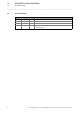
1 About this documentation 1.1 Document history ________________________________________________________________ 1.1 Document history Version 6 Description 1.0 03/2009 TD17 Field test version 2.0 06/2009 TD17 General revision 3.0 11/2009 TD17 General revision 4.0 02/2014 TD17 • New layout • General updates Lenze · E94AYCIB communication module (INTERBUS) · Communication Manual · DMS 4.
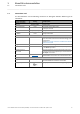
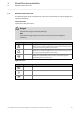
1 About this documentation 1.2 Conventions used ________________________________________________________________ 1.2 Conventions used This documentation uses the following conventions to distinguish between different types of information: Type of information Writing Examples/notes Spelling of numbers Decimal Decimal separator Hexadecimal Binary • Nibble Normal spelling Point 0x[0 ... 9, A ... F] In inverted commas Point Example: 1234 The decimal point is always used. For example: 1234.
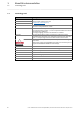
1 About this documentation 1.3 Terminology used ________________________________________________________________ 1.3 Terminology used Term Meaning Drive Lenze inverter of the "Servo Drives 9400" product series, with which the communication module can be used. Application as directed ( 12) Inverter Standard device Code Parameter which serves to parameterise and monitor the drive. In normal usage, the term is usually referred to as "Index".
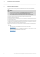
1 About this documentation 1.4 Definition of the notes used ________________________________________________________________ 1.
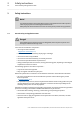
2 Safety instructions 2.1 General safety and application notes ________________________________________________________________ 2 Safety instructions Note! It is absolutely vital that the stated safety measures are implemented in order to prevent serious injury to persons and damage to material assets. Always keep this documentation to hand in the vicinity of the product during operation. 2.
2 Safety instructions 2.2 Device and application-specific safety instructions ________________________________________________________________ 2.2 Device and application-specific safety instructions • During operation, the communication module must be securely connected to the standard device. • With external voltage supply, always use a separate power supply unit, safely separated to EN 61800-5-1 in every control cabinet (SELV/PELV). • Only use cables corresponding to the given specifications.
3 Product description 3.1 Application as directed ________________________________________________________________ 3 Product description 3.1 Application as directed The communication module ... • is an accessory module that can be used in conjunction with the following standard devices: Product series Type designation Servo Drives 9400 HighLine E94AxHExxx From hardware version From software version 1A 03.00 Servo Drives 9400 PLC E94AxPExxxx VA 02.
3 Product description 3.3 Product features ________________________________________________________________ 3.3 Product features • Interface module for the INTERBUS communication system to be connected to the expansion slots of the Servo Drives 9400 • The communication module can either be supplied internally by the standard device or externally by a separate voltage source.
3 Product description 3.4 Terminals and interfaces ________________________________________________________________ 3.4 Terminals and interfaces S205 DIP switches for setting the ...
4 Technical data 4.1 General data and operating conditions ________________________________________________________________ 4 Technical data 4.
4 Technical data 4.2 Protocol data ________________________________________________________________ 4.2 Protocol data Range Values Process data words 0 ... 10 words (16 bits/word) Parameter data words 0, 1, 2, 4 words (16 bits/word) The parameter data is transmitted in accordance with the Peripherials Communication Protocol (PCP). Supported PMS services 4.
4 Technical data 4.4 Protective insulation ________________________________________________________________ 4.4 Protective insulation Danger! Dangerous voltage If the Servo Drives 9400 are operated on a phase earthed mains with a rated mains voltage 400 V, external measures need to be implemented in order to ensure protection against accidental contact.
4 Technical data 4.4 Protective insulation ________________________________________________________________ The following illustration ... • shows the arrangement of the terminal strips and the separate potential areas of the Servo Drive 9400. • serves to determine the decisive protective insulation between two terminals located in differently insulated separate potential areas. Note! The INTERBUS input (X206) is isolated from the voltage supply (X205) and the INTERBUS output (X207).
4 Technical data 4.4 Protective insulation ________________________________________________________________ Terminal strip Connection Terminal strip Connection X100 L1, L2, L3 (Single Drive only) X1 CAN on board 9400 +UG, -UG X2 State bus X105 U, V, W 24 V (ext.
4 Technical data 4.5 Dimensions ________________________________________________________________ 4.5 Dimensions a 89 mm b 134 mm b1 87 mm e 23 mm E94YCXX005 [4-2] 20 Dimensions Lenze · E94AYCIB communication module (INTERBUS) · Communication Manual · DMS 4.
5 Installation ________________________________________________________________ 5 Installation Stop! Electrostatic discharge Electronic components within the communication module can be damaged or destroyed by electrostatic discharge. Possible consequences • The communication module is defective. • Fieldbus communication is not possible or faulty. Protective measures • Before touching the module, be sure that you are free of electrostatic charge.
5 Installation 5.1 Mechanical installation ________________________________________________________________ 5.1 Mechanical installation 5.1.1 Assembly E94YCXX001G [5-1] 5.1.2 Assembly Disassembly E94AYCXX001H [5-2] 22 Disassembly Lenze · E94AYCIB communication module (INTERBUS) · Communication Manual · DMS 4.
5 Installation 5.2 Electrical installation ________________________________________________________________ 5.2 Electrical installation 5.2.1 Documentation for the standard device, host (PLC, master), system/machine Observe the notes and wiring instructions contained in this documentation. Wiring according to EMC guidelines In typical systems, standard shielding is sufficient for the INTERBUS cable.
5 Installation 5.2 Electrical installation ________________________________________________________________ 5.2.2 Wiring of the INTERBUS For communication with the master and all further components, Servo Drives 9400 have to be assembled with communication modules. The INTERBUS system has to be designed as a ring. Here, go and return lines are integrated in the same bus cable. The ring comes from the INTERBUS master via all other nodes back again to the master.
5 Installation 5.2 Electrical installation ________________________________________________________________ 5.2.3 INTERBUS connection The INTERBUS of the communication module is connected via the 9-pole Sub-D plug X206 (input) and the 9-pole Sub-D socket X207 (output).
5 Installation 5.2 Electrical installation ________________________________________________________________ Assignment of the 9-pole Sub-D socket X207 (OUT) 5.2.4 Pin Name Input/output Description 1 DO2 Output RS485: DO2 not inverted 2 DI2 Input RS485: DI2 not inverted 3 GND 4 GND 5 Vcc5 Output 5 V DC 6 /DO2 Output RS485: DO2 inverted 7 /DI2 Input RS485: DI2 inverted 8 Vcc5 Output 5 V DC 9 RBST Signalling input Connection to the outgoing INTERBUS is plugged.
5 Installation 5.2 Electrical installation ________________________________________________________________ 5.2.5 Bus cable specification The nodes at the bus system must be wired with one of the fieldbus cables that complies with the INTERBUS specification. A manufacturer of INTERBUS cables is e.g. PHOENIX CONTACT (Germany).
5 Installation 5.2 Electrical installation ________________________________________________________________ 5.2.7 External voltage supply The communication module can be externally supplied with voltage via separate supply cables at the 2-pin plug connector X205. Note! With external voltage supply, always use a separate power supply unit, safely separated to EN 61800-5-1 in every control cabinet (SELV/PELV).
6 Commissioning 6.1 Before initial switch-on ________________________________________________________________ 6 Commissioning During commissioning, system-related data such as motor parameters, operating parameters, responses, and parameters for fieldbus communication are defined in the inverter. For Lenze devices, this is done by means of codes. The codes of the inverter and for communication are saved to the memory module in a non-volatile data set.
6 Commissioning 6.2 Possible settings via DIP switch ________________________________________________________________ 6.2 Possible settings via DIP switch The following can be set via the S205 DIP switch: • Number of the process data words switches: 1 ... 4 ( 31) • Number of the parameter data words switches: 5 and 6 ( 32) • Baud rate switch: 8 ( 33) Lenze setting: All switches "OFF" Switch 7 has no function.
6 Commissioning 6.2 Possible settings via DIP switch ________________________________________________________________ 6.2.1 Setting the number of process data words • The number of process data words can be set via the switches 1 ... 4. • 0 ... 10 process data words can be used. • The current setting is displayed in the »Engineer« in C13860/2 / C14860/2. Note! The data word sum (process data word + parameter data words) has to consist of 1 ... 10 words (16 bits/word).
6 Commissioning 6.2 Possible settings via DIP switch ________________________________________________________________ 6.2.2 Setting the number of parameter data words • The number of parameter data words can be set via the switches 5 and 6. • 0, 1, 2 order 4 parameter data words can be used. • The current setting is displayed in the »Engineer« in C13860/1 / C14860/1. Note! The data word sum (process data word + parameter data words) has to consist of 1 ... 10 words (16 bits/word).
6 Commissioning 6.2 Possible settings via DIP switch ________________________________________________________________ 6.2.3 Setting the baud rate Note! Select the baud rate which depends on the data volume, cycle time, and number of nodes just high enough to suit your application. • The baud rate can be set via the switch 8. • Set the baud rate according to the length of the bus cable between the single INTERBUS nodes. • The current setting is displayed in the »Engineer« in C13863 / C14863.
6 Commissioning 6.3 Settings in »Engineer« ________________________________________________________________ 6.3 Settings in »Engineer« Note! The data word sum (process data words + parameter data words) has to consist of 1 ... 10 words (16 bits/word). Impermissible settings are reported by the BE LED (red blinking).
6 Commissioning 6.4 Initial switch-on ________________________________________________________________ 6.4 Initial switch-on Documentation for the standard device Note! Observe the safety instructions and information on residual hazards. Establishing communication In order to establish communication via an externally supplied communication module, the standard device must be switched on as well.
7 Data transfer ________________________________________________________________ 7 Data transfer The INTERBUS transmits parameter data, configuration data, diagnostic data, alarm messages and process data between the host (master) and the inverters (slaves) participating in the fieldbus. Depending on their time-critical nature, the data are transmitted via different communication channels. Communication channels The process data channel transmits process data.
8 Process data transfer ________________________________________________________________ 8 Process data transfer Configuring process data (PDO mapping) The Servo Drives 9400 enable the individual mapping of process data. For this purpose, the »Engineer« is provided with a port configurator. Note! • The port mapping for the Servo Drive 9400 is no configuration that can be carried out online.
8 Process data transfer ________________________________________________________________ 3. Click the Edit PDO button. The selection window for editing the process data object is opened: Here you can transfer the individual ports from the Port Selection list to the receive PDO "PDO_RX0" by clicking the >> button. The Up and Down buttons serve to shift the sequence of the ports within the PDOs. 4. Confirm the selection with OK. 5. Repeat the steps 2. to 4. for the transmit object PDO_TX0. 6.
9 Parameter data transfer 9.1 Addressing of the parameter data ________________________________________________________________ 9 Parameter data transfer The parameter data of Lenze devices are contained in codes which are listed in this documentation and the documentation of the Servo Drive 9400. Parameter reference ( 53) 9.1 Addressing of the parameter data The parameters of a Lenze device are not directly addressed via codes but via an index and subindex.
9 Parameter data transfer 9.2 Initialising PCP communication ________________________________________________________________ 9.2 Initialising PCP communication Make entries into the CRL (communication relation list) in order that communication between the INTERBUS master and the communication module can take place.
9 Parameter data transfer 9.3 Supported PMS services ________________________________________________________________ 9.3 Supported PMS services The parameter data is transferred via PMS services. In the following, only parameters and their contents are given that are returned by the Lenze inverters. All other transfer parameters of the given PMS services can be obtained from the corresponding descriptions of the INTERBUS master.
9 Parameter data transfer 9.3 Supported PMS services ________________________________________________________________ 9.3.4 Read/Write The "Read" PMS service reads parameters from the inverter. The inverter outputs the requested parameter or an error message. The "Write" PMS service writes on parameters of the inverter. The inverter outputs a positive feedback or an error message. The following error messages can occur: 9.3.
9 Parameter data transfer 9.3 Supported PMS services ________________________________________________________________ 9.3.6 Identify The P "Identify" MS service provides information on how to identify the inverter.
9 Parameter data transfer 9.3 Supported PMS services ________________________________________________________________ 9.3.7 Status The "Status" PMS service provides status information about the inverter.
10 Monitoring 10.1 Interruption of the INTERBUS communication ________________________________________________________________ 10 Monitoring 10.1 Interruption of the INTERBUS communication An interruption of the INTERBUS communication, e.g. by cable break or failure of the host (PLC, master), is recognised by the communication module.
10 Monitoring 10.2 Interruption of internal communication ________________________________________________________________ 10.2 Interruption of internal communication The response to a communication error between the communication module and the Servo Drive 9400 can be set via these codes: • C01501 (module in slot MXI1) • C01502 (module in slot MXI2) 46 Lenze · E94AYCIB communication module (INTERBUS) · Communication Manual · DMS 4.
11 Diagnostics 11.1 LED status displays ________________________________________________________________ 11 Diagnostics For purposes of fault diagnostics, the communication module is provided with the LEDs on the front. Furthermore you can carry out the Diagnosing with the »Engineer« ( 48). 11.1 LED status displays Note! During normal operation, the LED BS blinks and the LED MS is permanently lit. LEDs Pos.
11 Diagnostics 11.2 Diagnosing with the »Engineer« ________________________________________________________________ 11.2 Diagnosing with the »Engineer« In the »Engineer« under the Diagnostics tab, you will find INTERBUS diagnostics information. Querying the current bus status C13861 / C14861 displays the bus status of the INTERBUS node: Value C13861/14861 [hex] Bus status Description 0xyyy0 IBS-INIT Initialisation 0xyyy1 IBS-ACTIVE The bus is active. Data cycles are executed.
12 Error messages 12.1 Short overview of the INTERBUS error messages ________________________________________________________________ 12 Error messages This chapter supplements the error list for the Servo Drive 9400 contained in the reference manual and in the »Engineer« online help with the error messages of the communication module. 12.1 Reference manual/»Engineer« online help for the Servo Drive 9400 Here you will find general information on diagnostics & fault analysis and on error messages.
12 Error messages 12.2 Possible causes and remedies ________________________________________________________________ 12.2 Possible causes and remedies This chapter lists all INTERBUS error messages in the numerical order of the error numbers. Possible causes and remedies as well as responses to the error messages are described in detail.
12 Error messages 12.2 Possible causes and remedies ________________________________________________________________ INTERBUS: Internal error [0x00c86101] Response (Lenze setting printed in bold) Setting: not possible None System fault Fault Trouble Quick stop by trouble Warning locked Warning Information Cause Remedy Internal error Send module with error description to Lenze.
12 Error messages 12.2 Possible causes and remedies ________________________________________________________________ INTERBUS: Invalid initialisation [0x00c88127] Response (Lenze setting printed in bold) Setting: not possible None System error Error Fault Quick stop by trouble Warning locked Warning Information Cause Remedy The INTERBUS initialisation has failed. Execute renewed initialisation by the master.
13 Parameter reference 13.1 Parameters of the standard device that are relevant to communication ________________________________________________________________ 13 Parameter reference This chapter supplements the parameter list and the table of attributes contained in the reference manual and in the »Engineer« online help for the Servo Drive 9400 with the parameters of the E94AYCIB (INTERBUS) communication module. 13.
13 Parameter reference 13.1 Parameters of the standard device that are relevant to communication ________________________________________________________________ C00637 Parameter | Name: C00637 | Resp. to new module in MXI2 Data type: UNSIGNED_32 Index: 23939 = 0x5D83 Response if a new module has been plugged into module slot 2 of the standard device.
13 Parameter reference 13.2 Parameters of the communication module for slot MXI1 ________________________________________________________________ 13.2 Parameters of the communication module for slot MXI1 This chapter lists the parameters of the E94AYCIB communication module (INTERBUS) for slot MXI2 of the Servo Drive 9400 in numerically ascending order.
13 Parameter reference 13.2 Parameters of the communication module for slot MXI1 ________________________________________________________________ C13789 Parameter | Name: Data type: UNSIGNED_8 Index: 10786 = 0x2A22 C13789 | Service code This code is for device-internal use only and must not be written to by the user. Setting range (min. value | unit | max.
13 Parameter reference 13.2 Parameters of the communication module for slot MXI1 ________________________________________________________________ C13852 Parameter | Name: Data type: UNSIGNED_16 Index: 10723 = 0x29E3 C13852 | All words to the basic device Display of the process data words which are transmitted from the communication module to the standard device. • In the subcodes 1 ... 32, all process data words from the communication module are displayed. Display area (min. value | unit | max.
13 Parameter reference 13.2 Parameters of the communication module for slot MXI1 ________________________________________________________________ C13855 Parameter | Name: Data type: UNSIGNED_8 Index: 10720 = 0x29E0 C13855 | Length of ports mapped into send PDO Display of the total data length (in bytes) of the ports that have been entered into the send PDO. The data word sum (process data words + parameter data words) has to consist of 1 ... 10 words (16 bits/word).
13 Parameter reference 13.2 Parameters of the communication module for slot MXI1 ________________________________________________________________ C13862 Parameter | Name: Data type: UNSIGNED_16 Index: 10713 = 0x29D9 C13862 | Counter Counter for cycles and INTERBUS resets Display area (min. value | unit | max.
13 Parameter reference 13.2 Parameters of the communication module for slot MXI1 ________________________________________________________________ C13881 Parameter | Name: C13881 | Response time if the INTERBUS communication is interrupted Data type: UNSIGNED_16 Index: 10694 = 0x29C6 If the "IBS-ACTIVE" status (INTERBUS is active and data is cyclically exchanged) is quit, the response parameterised in C13880/1 is executed after the monitoring time set for the data exchange has elapsed.
13 Parameter reference 13.2 Parameters of the communication module for slot MXI1 ________________________________________________________________ C13893 Parameter | Name: Data type: UNSIGNED_8 Index: 10682 = 0x29BA C13893 | Process data length Setting of the number of the process data words to be used The setting is activated ...
13 Parameter reference 13.2 Parameters of the communication module for slot MXI1 ________________________________________________________________ C13901 Parameter | Name: Data type: VISIBLE_STRING Index: 10674 = 0x29B2 C13901 | Firmware compilation date Display of the compilation date of the firmware (string with a length of 20 bytes) • The date ("MMM TT JJJJ") and the time ("hh:mm:ss") are output, e.g. "Mar 21 2005 12:31:21".
13 Parameter reference 13.3 Parameters of the communication module for slot MXI2 ________________________________________________________________ 13.3 Parameters of the communication module for slot MXI2 This chapter lists the parameters of the E94AYCIB communication module (INTERBUS) for slot MXI2 of the Servo Drive 9400 in numerically ascending order.
13 Parameter reference 13.3 Parameters of the communication module for slot MXI2 ________________________________________________________________ C14789 Parameter | Name: Data type: UNSIGNED_8 Index: 9786 = 0x263A C14789 | Service code This code is for device-internal use only and must not be written to by the user! Setting range (min. value | unit | max.
13 Parameter reference 13.3 Parameters of the communication module for slot MXI2 ________________________________________________________________ C14852 Parameter | Name: Data type: UNSIGNED_16 Index: 9723 = 0x25FB C14852 | All words to standard device Display of the process data words 1 ... 32 transferred from the communication module to the standard device. • In the subcodes 1 ... 32, all process data words from the communication module are displayed. Display area (min. value | unit | max.
13 Parameter reference 13.3 Parameters of the communication module for slot MXI2 ________________________________________________________________ C14855 Parameter | Name: Data type: UNSIGNED_8 Index: 9720 = 0x25F8 C14855 | Length of ports mapped into send PDO Display of the total data length (in bytes) of the ports that have been entered into the send PDO. The data word sum (process data words + parameter data words) has to consist of 1 ... 10 words (16 bits/word).
13 Parameter reference 13.3 Parameters of the communication module for slot MXI2 ________________________________________________________________ C14862 Parameter | Name: Data type: UNSIGNED_16 Index: 9713 = 0x25F1 C14862 | Counter Counter for cycles and INTERBUS resets Display area (min. value | unit | max.
13 Parameter reference 13.3 Parameters of the communication module for slot MXI2 ________________________________________________________________ C14881 Parameter | Name: C14881 | Response time if the INTERBUS communication is interrupted Data type: UNSIGNED_16 Index: 9694 = 0x25DE If the "IBS-ACTIVE" status (INTERBUS is active and data is cyclically exchanged) is quit, the response parameterised in C14880/1 is executed after the monitoring time set for the data exchange has elapsed.
13 Parameter reference 13.3 Parameters of the communication module for slot MXI2 ________________________________________________________________ C14893 Parameter | Name: Data type: UNSIGNED_8 Index: 9682 = 0x25D2 C14893 | Process data length Setting of the number of the process data words to be used The setting is activated ...
13 Parameter reference 13.3 Parameters of the communication module for slot MXI2 ________________________________________________________________ C14901 Parameter | Name: Data type: VISIBLE_STRING Index: 9674 = 0x25CA C14901 | Firmware compilation date Display of the compilation date of the firmware (string with a length of 20 bytes) • The date ("MMM TT JJJJ") and the time ("hh:mm:ss") are output, e.g. "Mar 21 2005 12:31:21".
13 Parameter reference 13.4 Table of attributes ________________________________________________________________ 13.4 Table of attributes The table of attributes contains information required for communication with the inverter via parameters. How to read the table of attributes: Column Meaning Code Parameter name Cxxxxx Name Parameter short text (display text) Text hex Index under which the parameter is addressed. The subindex for array variables corresponds to the Lenze subcode number.
13 Parameter reference 13.
13 Parameter reference 13.4 Table of attributes ________________________________________________________________ Code Name Index Data dec hex DS DA DT Access Factor R C14902 Firmware version 9673 0x25C9 E 1 VISIBLE_STRING C14920 Display of DIP switch position 9655 0x25B7 E 1 BITFIELD_8 Lenze · E94AYCIB communication module (INTERBUS) · Communication Manual · DMS 4.
Index ________________________________________________________________ 14 Index A Abort (PMS service) 41 Active baud rate (C13863) 59 Active baud rate (C14863) 67 Addressing of the parameter data 39 All words from drive to master (C13850) 56 All words from master to drive (C13851) 56 All words from the master (C14851) 64 All words from the standard device (C14853) 65 All words to the basic device (C13852) 57 All words to the basic device (C13853) 57 All words to the master (C14850) 64 All words to the sta
Index ________________________________________________________________ D G Data transfer 36 Device and application-specific safety instructions 11 Device identification 15 Device protection 11 Diagnostics 47 Diagnostics with the »Engineer« 48 Dimensions 20 Dimensions of 9-pole Sub-D connectors 26 DIP switch settings 30 Disassembly 22 Display of DIP switch position (C13920) 62 Display of the DIP switch position (C14920) 70 Document history 6 General data 15 General safety and application notes 10 Get-OD
Index ________________________________________________________________ M R Max. number of data words 15 Max. PDU length 15 Mechanical installation 22 Module ID 15 Monitoring 45 Monitoring Reaction (C13880) 59 Read (PMS service) 42 Reject (PMS service) 41 Residual hazards 11 Resp. to comm. error with MXI1 (C01501) 54 Resp. to comm. error with MXI2 (C01502) 54 Resp. to imp. device config. (C00615) 53 Resp. to new module in MXI1 (C00636) 53 Resp.
)(('%$&. Your opinion is important to us These instructions were created to the best of our knowledge and belief to give you the best possible support for handling our product. Perhaps we have not succeeded in achieving this objective in every respect. If you have suggestions for improvement, please e-mail us to: feedback-docu@lenze.com Thank you very much for your support.
E94AYCIB communication module (INTERBUS) · Communication Manual · EDS94AYCIB · 13451099 · DMS 4.0 EN · 02/2014 · TD17 Lenze Automation GmbH Postfach 10 13 52, D-31763 Hameln Hans-Lenze-Straße 1, D-31855 Aerzen Germany +49 5154 82-0 +49 5154 82-2800 lenze@lenze.com www.lenze.com Service Lenze Service GmbH Breslauer Straße 3, D-32699 Extertal Germany 008000 24 46877 (24 h helpline) +49 5154 82-1112 service@lenze.