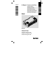
Ä.>Kôä EDK94AZCUS .
, Lesen Sie zuerst diese Anleitung, bevor Sie mit den Arbeiten beginnen! Beachten Sie die enthaltenen Sicherheitshinweise. , Please read these instructions before you start working! Follow the enclosed safety instructions. , Veuillez lire attentivement cette documentation avant toute action ! Les consignes de sécurité doivent impérativement être respectées. , Lea las instrucciones antes de empezar a trabajar. Observe las instrucciones de seguridad indicadas.
E894ZCUS001BA klappseite E94ZAZCUS
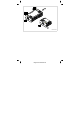
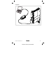
Lieferumfang Pos. Beschreibung USB−Diagnoseadapter E94AZCUS USB−Kabel Montageanleitung Anschlüsse Pos. Beschreibung X61 USB−Anschluss X6 Anschluss des Grundgerätes (RJ69−Buchse) Anzeigen Pos. Farbe Zustand Beschreibung Power grün an Diagnoseadapter ist vom Grundgerät mit Spannung versorgt. Tx / Rx gelb blinkt Grundgerät und PC kommunizieren miteinander über den Diagnoseadapter. USB grün an Diagnoseadapter ist über USB mit dem PC verbunden und konfiguriert.
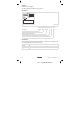
Anschlussbild E94ZCUS002 EDK94AZCUS DE/EN/FR/ES/IT 4.
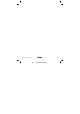
Gültigkeit Diese Anleitung ist gültig für ƒ USB−Diagnoseadapter E94AZCUS ab Version VA. Identifikation E94ZCUS003 E94 A Z C US VA Produktreihe Gerätegeneration Modulkennung: Zubehör Modultyp: Kommunikationsmodul USB−Diagnoseadapter Hardwarestand Einsetzbarkeit Die Verwendung dieses Kommunikationszubehörs ist zulässig mit Grundgeräten der Produktreihe 9400 ab der Typenschildbezeichnung l Type E94AxxExxxx l HW: PC l SW : 0.10 6 l EDK94AZCUS DE/EN/FR/ES/IT 4.
EDK94AZCUS DE/EN/FR/ES/IT 4.
Scope of supply Pos. Description USB diagnostic adapter E94AZCUS USB cable Mounting Instructions Connections Pos. Description X61 USB connection X6 Connection of the basic device (RJ69 socket) Displays Pos. Colour Condition Description Power Green On Diagnostic adapter is supplied with voltage by the basic device. Tx / Rx Yellow Blinking Basic device and PC communicate with each other via the diagnostic adapter.
Connection diagram E94ZCUS002 EDK94AZCUS DE/EN/FR/ES/IT 4.
Validity These instructions are valid for ƒ USB diagnostic adapter E94AZCUS as of version VA. Identification E94ZCUS003 E94 A Z C US VA Product series Device generation Module identification: accessories Module type: communication module USB diagnostic adapter Hardware version Application range This communication accessory may be used in conjunction with basic devices of the 9400 product series as of nameplate designation l Type E94AxxExxxx l HW: PC l SW : 0.
EDK94AZCUS DE/EN/FR/ES/IT 4.
Equipement livré Pos. Description Adaptateur de diagnostic USB E94AZCUS Câble USB Instructions de montage Raccordements Pos. Description X61 Raccordement USB X6 Raccordement de l’appareil de base (prise RJ69) Affichages Pos. Couleur Etat Description Power LED verte ON L’adaptateur de diagnostic est alimenté par l’appareil de base. Tx / Rx LED jaune clignote L’appareil et l’ordinateur communiquent via l’adaptateur de diagnostic.
Schéma de raccordement E94ZCUS002 EDK94AZCUS DE/EN/FR/ES/IT 4.
Validité Le présent document s’applique au produit suivant : ƒ aux adaptateurs de diagnostic USB E94AZCUS à partir de la version VA.
EDK94AZCUS DE/EN/FR/ES/IT 4.
Contenido del suministro Pos. Descripción Adaptador de diagnóstico E94AZCUS Cable USB Instrucciones para el montaje Conexiones Pos. Descripción X61 Conexión USB X6 Conexión del equipo básico (conector RJ69) Indicadores Pos. Color Estado Descripción Power verde encendido El adaptador de diagnóstico es alimentado por el equipo básico. Tx / Rx amarill o parpadea El equipo básico y el PC se están comunicando a través del adaptador de diagnóstico.
Esquema de conexiones E94ZCUS002 EDK94AZCUS DE/EN/FR/ES/IT 4.
Validez Este manual es de aplicación para ƒ Adaptador de diagnóstico USB E94AZCUS a partir de la versión VA.
EDK94AZCUS DE/EN/FR/ES/IT 4.
Oggetto della fornitura Pos. Descrizione Adattatore per diagnostica USB E94AZCUS Cavo USB Istruzioni di montaggio Collegamenti Pos. Descrizione X61 Collegamento USB X6 Collegamento del modulo asse (connettore RJ69) Indicazioni luminose Pos. Colore Stato Descrizione Power verde acceso L’adattatore per diagnostica riceve la tensione di alimentazione dal modulo asse. Tx / Rx giallo lampeggiant e Il modulo asse e il PC comunicano tra loro tramite l’adattatore per diagnostica.
Schema di collegamento E94ZCUS002 EDK94AZCUS DE/EN/FR/ES/IT 4.
Validità La presente documentazione è valida per ƒ Adattatore per diagnostica USB E94AZCUS a partire dalla versione VA. Identificazione E94ZCUS003 E94 A Z C US VA Serie prodotto Versione Identificazione modulo: accessorio Tipo di modulo: modulo di comunicazione Adattatore per diagnostica USB Versione hardware Compatibilità Questo accessorio di comunicazione può essere utilizzato con moduli asse della serie 9400 a partire dalla versione seguente: l Tipo E94AxxExxxx l HW: PC l SW: 0.
EDK94AZCUS DE/EN/FR/ES/IT 4.
© 06/2010 F ( Ê ü Lenze Automation GmbH Hans−Lenze−Str. 1 D−31855 Aerzen Germany +49 (0)51 54 / 82−0 +49 (0)51 54 / 82 − 28 00 Lenze@Lenze.de Service Lenze Service GmbH Breslauer Straße 3 D−32699 Extertal Germany ( Ê 00 80 00 / 24 4 68 77 (24 h helpline) +49 (0)51 54 / 82−11 12 Service@Lenze.de www.Lenze.com EDK94AZCUS § .>Kô § DE/EN/FR/ES/IT § 4.