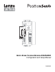
MOTOR BRAKE MODULE BRAKE RELEASED + – 24VDC + – BRAKE Motor Brake Terminal Module E94ZAHBK2 Configuration and Setup Manual P940HBK01B
Table of Contents 1 Safety Information . . . . . . . . . . . . . . . . . . . . . . . . . . 3 1.1 Persons Responsible for Safety . . . . . . . . . . . . . . . . . . . . 3 1.2 General Safety Information . . . . . . . . . . . . . . . . . . . . . . . 4 2 General Information . . . . . . . . . . . . . . . . . . . . . . . . . 4 2.1 How to use these Operating Instructions . . . . . . . . . . . . . . . .
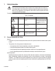
1 Safety Information WARNING! When operating the PositionServo drive remotely with an output module, the motor may start unexpectedly, which could result in damage to equipment and/or injury to personnel. Make sure the equipment is free to operate in this manner, and that all guards and covers are in place to protect personnel. The pictographs in Table 1 are used in AC Technolgy documentation to provide safety information. Table 1: Pictographs Pictograph 1.
1.2 General Safety Information WARNING! When operating the PositionServo drive remotely with an output module, the motor may start unexpectedly, which could result in damage to equipment and/or injury to personnel. Make sure the equipment is free to operate in this manner, and that all guards and covers are in place to protect personnel. • These safety notes do not claim to be complete. In case of questions and problems please contact your Lenze representative.
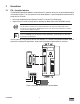
3 Connections 3.1 P3A - Controller Interface The E94ZAHBK2 Motor Brake Module is mounted to the P3 connector on the face of the PositionServo drive as illustrated in Figure 1. The P3A connector on the Brake Module is a pass-through SCSI connector from P3 except for pins 45 and 46. • Refer to the PositionServo Users Manaual, Section 5.1.3 for the P3 Pin Assignments. • Output 2 (Pins 45 and 46) are dedicated for controlling the Motor Brake on the E94ZAHBK2 module.
3.2 J1 - Terminal Block The J1 terminal block consists of 4 terminals at the base of the E94ZAHBK2 Motor Brake Module. The two left terminals are for the external 24 VDC power supply that will energize the brake coil. The two terminals on the right are to be wired to the brake coil.
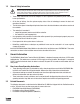
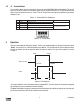
4.1 Parameters Refer to the PositionServo Programming Manual (PM94P01) for a complete list of accessible variables with which to program the drive. The variables in Table 3 pertain to the use of digital outputs. Table 3: Index Variables 4.
WAITENABLE: WAIT UNTIL IN_A3 ENABLE WAIT TIME 1000 OUT2 = 1 WAIT TIME 1000 VAR_REFERENCE = 0 OUT1 = 0 V0 = 0 Again: GOTO Again END ; ; ; ; ; ; ; wait until A3 - hardware “enable” closed enable/start drive (& brake if assigned) wait 1 second to release brake Release Brake Wait 1 sec.
AC Technology Corporation member of the Lenze Group 630 Douglas Street Uxbridge, MA 01569 Telephone: (508) 278-9100 Facsimile: (508) 278-7873 P940HBK01B