PositionServo with MVOB Mounting Instructions
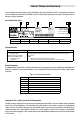
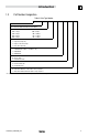
About These Instructions These mounting instructions pertain to the PositionServo drive with Hardware Version 2. Read both this document and the PositionServo User Manual (S94H201) in their entirety before operating or servicing a PositionServo drive. Observe all safety instructions. Drive Identification Label A B C Type: E94P120Y2NES ID-No: 13014745 Made in USA D E F INPUT: 1(3)/PE OUTPUT: 3/PE 120/240 V 0 - 230 V 12.0 A 24.0 (13.
Contents 1 2 3 Introduction.........................................................................................................................................2 1.1 Safety Information......................................................................................................................2 1.2 Legal Regulations......................................................................................................................2 1.3 Part Number Designation............................
Introduction 1 Introduction 1.1 Safety Information DANGER! Hazard of electrical shock! Circuit potentials are up to 480 VAC above earth ground. Avoid direct contact with the printed circuit board or with circuit elements to prevent the risk of serious injury or fatality. Disconnect incoming power and wait 60 seconds before servicing drive. Capacitors retain charge after power is removed.
Introduction 1.
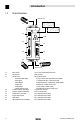
Introduction Drive Connectors L3 1.
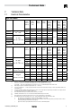
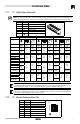
Technical Data 2 Technical Data 2.1 Electrical Characteristics Single-Phase Models Type (1) Mains Voltage (2) E94_020S1N_~ E94_040S1N_~ 120V (3) or 240V (4) E94_020S2F_~ E94_040S2F_~ E94_080S2F_~ 120 / 240V (80 V -0%...264 V +0%) (4) E94_100S2F_~ 1~ Mains Current (doubler) 1~ Mains Current (Std.
Technical Data 2.2 Connections and I/O 2.2.
Technical Data 2.2.2 P7 - Output Power Connection STOP! DO NOT connect incoming power to the output motor terminals (U, V, W)! Severe damage to the PositionServo will result.Check phase wiring (U, V, W) and thermal input (T1, T2) before powering up drive. If miswired, severe damage to the PositionServo will result.
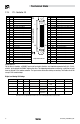
Technical Data P3 - Controller I/O Pin Name Function 1 MA+ Master Encoder A+ / Step+ input 2 MA- Master Encoder A- / Step- input 3 MB+ Master Encoder B+ / Direction+ input 4 MB- Master Encoder B- / Direction- input 5 GND Drive Logic Common 6 5+ +5V output (max 100mA) 7 BA+ Buffered Encoder Output: Channel A+ 8 BA- Buffered Encoder Output: Channel A9 BB+ Buffered Encoder Output: Channel B+ 10 BB- Buffered Encoder Output: Channel B11 BZ+ Buffered Encoder Output: Channel Z+ 12 BZ- Buffered Encoder Output: Cha
Technical Data P4 - Motor Feedback E94P E94R 2.2.
Technical Data 2.2.7 P6 - Braking Resistor and DC Bus Pin Terminal 1 2 3 4 5 B+ B+ BR BB- Function [mm2] [AWG] [mm] [in] [Nm] [lb-in] 2.5* 14 6* 0.25 0.5* 4.5 4 12 6 0.25 0.5 4.5 BR Positive DC Bus / Brake Resistor Brake Resistor BB- Negative DC Bus * For E94_120Y2N_~ and E94_180T2N_~ models use: 2.2.8 B+ B+ P8 - ISO 13849 Safety Circuit (Option) STOP! BEFORE using P8, read the COMPLETE DETAILED INSTRUCTIONS for the ISO 13849-1 Safety Circuit in Section 4.1.
Technical Data STOP! This is only partial information on the ISO 13849-1 Safety Circuit. BEFORE using P8, read the COMPLETE DETAILED INSTRUCTIONS for the ISO 13849-1 Safety Circuit in Section 4.1.8 of manual S94H201 (PositionServo Users Manual on the accompanying CD and www.lenzeamericas.com). Due to ISO 13849-1 regulations, a separate +24VDC external dedicated safety power supply must be provided to the drive Safety circuits.
Installation 3 Installation DANGER! Hazard of electrical shock! Circuit potentials are up to 480 VAC above earth ground. Avoid direct contact with the printed circuit board or with circuit elements to prevent the risk of serious injury or fatality. Disconnect incoming power and wait 60 seconds before servicing drive. Capacitors retain charge after power is removed. STOP! • The PositionServo must be mounted vertically for safe operation and to ensure enough cooling air circulation.
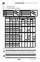
Installation 3.1 PositionServo Dimensions 34 dia = 4.57 12 D B 12 15 C (1) 4.57 38 A Dimensions in mm Type (1) A (mm) B (mm) C (mm) D (mm) Weight (kg) E94_020S1N_~ 68 190 190 182 1.1 E94_040S1N_~ 69 190 190 182 1.2 E94_020S2F_~ 68 190 235 182 1.3 E94_040S2F_~ 69 190 235 182 1.5 E94_080S2F_~ 87 190 235 182 1.9 E94_100S2F_~ 102 190 235 182 2.2 E94_020Y2N_~ 68 190 190 182 1.3 E94_040Y2N_~ 69 190 190 182 1.5 E94_080Y2N_~ 95 190 190 182 1.
Installation 3.2 Clearance for Cooling Air Circulation >25mm >3mm >3mm Additional Clearance is required: • for side mount and rear mount AC line filters • if there are other accessories installed • for cables and wires connected to the top, front and bottom of the drive • when the drive is mounted adjacent to noise sensitive equipment or clean wire ways >25mm 3.3 • • • Shielding and Grounding Use single-point grounding (SPG) for panel-mounted controls.
Installation 3.4 Electrical Installation These are quick connect instructions only. Consult PositionServo User Manual S94H201 for full connection details. Step Action 1 Connect the Drive’s Ethernet port P2 to your PC’s Ethernet port. Description Drive PC/Laptop Ethernet Port CAT 5e cable P2 P3 P4 2 Apply power to the drive and wait until “diS” shows on the display. 3 Confirm that the PC and the drive have the correct IP setting. (S94H201, section 6.2.2).
Lenze Americas Corporation • Lenze AC Tech Corporation 630 Douglas Street • Uxbridge, MA 01569 • USA Sales: (800) 217-9100 • Service (508) 278 9100 www.lenze.