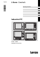
L−force Controls Ä.NnGä BA_ELx8xx .NnG Operating Instructions Industrial PC S1 Power Fail Status S8 S2 S9 S3 S10 S4 S11 S5 S12 S6 S13 S7 S14 F1 F2 + F3 - - + Power Fail Status / ( 7 F1 Esc F2 F3 F4 F5 F6 F7 F8 F9 F10 F11 F12 Enter ) 8 - 9 $ & 4 5 6 ! 1 2 = 3 > < , 0 + § " * A 7 / | B 8 F 5 Fail J 1 2 M Bs 0 .
Please read these instructions before you start working! Follow the enclosed safety instructions.
Contents 1 2 3 4 5 i About this documentation . . . . . . . . . . . . . . . . . . . . . . . . . . . . . . . . . . . . . . . . . . . . . . . . . . 5 1.1 Document history . . . . . . . . . . . . . . . . . . . . . . . . . . . . . . . . . . . . . . . . . . . . . . . . . . . . 6 1.2 Conventions used . . . . . . . . . . . . . . . . . . . . . . . . . . . . . . . . . . . . . . . . . . . . . . . . . . . . 7 1.3 Notes used . . . . . . . . . . . . . . . . . . . . . . . . . . . . . . . . . . . . . . . .
i 6 7 8 9 4 Contents Electrical installation . . . . . . . . . . . . . . . . . . . . . . . . . . . . . . . . . . . . . . . . . . . . . . . . . . . . . . . 36 6.1 Important notes . . . . . . . . . . . . . . . . . . . . . . . . . . . . . . . . . . . . . . . . . . . . . . . . . . . . . . 36 6.2 Wiring according to EMC . . . . . . . . . . . . . . . . . . . . . . . . . . . . . . . . . . . . . . . . . . . . . . 37 6.5 Connecting the supply and peripheral devices . . . . . . . . . . . . . . . . . .
About this documentation 1 0Fig. 0Tab. 0 1 About this documentation Contents This documentation provides you with information about the intended use of the Industrial PC. The present manual is part of the "PC−based automation" manual collection which you can find on the DVDs of the same name. Target group This documentation is directed at qualified skilled personnel according to IEC 60364.
1 About this documentation Document history 1.1 Document history Material number 6 Version Description .NnG 3.0 02/2014 TD06 New: l UL notes (French language) l Notes RJ45 cable laying 13433080 2.0 03/2013 TD29 General revision 13391236 1.3 10/2011 TD29 Supplement of the note concerning the protection against direct solar radiation, as well as revision of the sections ˆReplacing the battery˜ and ˆReplacing the fuse˜. 13370129 1.
About this documentation 1 Conventions used 1.2 Conventions used This documentation uses the following conventions to distinguish between different types of information: Type of information Identification Examples/notes Spelling of numbers Point Decimal separator In general, the decimal point is used. For instance: 1234.
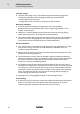
1 About this documentation Notes used 1.3 Notes used The following pictographs and signal words are used in this documentation to indicate dangers and important information: Safety instructions Structure of safety instructions: Danger! (characterises the type and severity of danger) Note (describes the danger and gives information about how to prevent dangerous situations) Pictograph and signal word Meaning Danger! Danger of personal injury through dangerous electrical voltage.
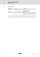
Safety instructions 2 General safety information 2 Safety instructions 2.1 General safety information Scope The following general safety instructions apply to all Lenze drive and automation components. The product−specific safety and application notes given in this documentation must be observed! For your own safety Danger! Disregarding the following basic safety measures may lead to severe personal injury and damage to material assets! BA_ELx8xx EN 3.0 ƒ Lenze drive and automation components .
2 Safety instructions General safety information Transport, storage ƒ Transport and storage in a dry, low−vibration environment without aggressive atmosphere; preferably in the packaging provided by the manufacturer. – Protect against dust and shocks. – Comply with climatic conditions according to the technical data. Mechanical installation ƒ Install the product according to the regulations of the corresponding documentation.
Safety instructions 2 General safety information Maintenance and servicing ƒ The components are maintenance−free if the required operating conditions are observed. ƒ If the cooling air is polluted, the cooling surfaces may be contaminated or the air vents may be blocked. Under these operating conditions, the cooling surfaces and air vents must be cleaned at regular intervals.
2 Safety instructions Product−specific safety instructions 2.2 12 Product−specific safety instructions ƒ Protect the device against direct solar radiation, since the housing may heat up strongly. ƒ The device is classified as a class A device and can cause radio interference in residential areas. In this case, the operator may have to take special measures. Any costs arising from these measures have to be paid by the operator. ƒ A touchscreen does not comply with the Ergonomics Directive ZH 1/618.
Safety instructions 2 Safety instructions for the installation according to UL 2.3 Safety instructions for the installation according to UL Original − English Approval Underwriter Laboratories (UL), UL508 and CSA C22.2 No. 142−M1987, (UL File Number E236341) Ratings ƒ Input 24 V DC, 65 W ƒ Max. Ambient Temperature 40 °C – EL6xx, EL1xxx, EL5xxx, EL9xxx only ƒ Max. Surrounding Temperature 50 °C – EL8xx, EL2xxx, EL7xxx only ƒ Optional communication ratings: – RS232−Connection: max.
2 Safety instructions Safety instructions for the installation according to UL Original − French Homologation Underwriter Laboratories (UL), UL508 et CSA C22.
Product description 3 Scope of supply 3 Product description 3.1 Scope of supply Quanti Name ty 1 Embedded Line Panel PC 8 4 6 5 6 Screw clamp fixings EL 1800, EL 1800s, EL 1850, EL 1850s EL 2800 EL 2850, EL 5800, EL 5820, EL 5850 EL 5870 EL 9800 1 Connection plug for voltage supply 1 DVD "PC based Automation" 1 Test report 1 Device pass card Note! After receipt of the delivery, check immediately whether the items match the accompanying papers.
3 Product description Application as directed 3.2 Application as directed The industrial PC is used as directed if it is solely used for implementing control and operating concepts or for presenting information in usual industrial and commercial fields. A different use, or one beyond these purposes, is not permissible.
Product description 3 Device features 3.3 Device features EL x8xx Design l Mounting l Electrical supply l l Computer unit Ports PC housing made of sheet steel, in the case of passive cooling partly of aluminium l Front frame made of anodised and etched aluminium l Front with polyester foil For installation in control cabinets, control boards or machine enclosures 24 V DC voltage supply Lithium battery for buffering the real time clock (RTC) l ETX module with – Intelâ Atom N270, 1.
3 Product description Device features Overview Panel PC EL 1800 / EL 1800s / EL 2800 / EL 5800 / EL 9800 Thin Client EL 1800 TC / EL 1800s TC / EL 2800 TC / EL 5800 TC / EL 9800 TC l EL 1800 (TC): VGA touchscreen 26.4 cm (10.4") EL 1800s (TC): SVGA touchscreen 26.4 cm (10.4") EL 2800 (TC): SVGA touchscreen 30.7 cm (12.1") EL 5800 (TC): XGA touchscreen 38.1 cm (15") EL 9800 (TC): SXGA touchscreen 48.
Product description 3 Device features Panel PC EL 5870 Thin Client EL 5870 TC / ( 7 l l l ) 8 9 5 6 $ - XGA touchscreen 38.1 cm (15") 12 freely assignable function keys MF2 keyboard & 4 ! 1 2 = 3 > < , 0 + § " * / | Power Fail Status Bs Alt Gr - + F1 F2 Alt F3 Q W F4 E @ A S Y € F5 R F D X F6 T C Z G V F7 H B F8 U I J N K M F9 O μ Ü Ö L ; , F10 P : .
3 Product description Identification 3.4 Identification 31855 Aerzen; Germany Made in Germany Type 107AT12345 107AT12345 DVIUSB−012 Type designation Type code (catalogue/order no.) Technical data Customised material number Bar code with serial number Manufacturer address Certification CE mark Type code EL x8xx EP8GAP x x x 00 x x x x x 00− x x xx x x x x xxx Screen diagonal (resolution) 3 = 26.4 cm (10.4") / 640 x 480 pixels 4 = 26.4 cm (10.
Product description 3 Identification Type code EL x8xx EP8GAP x x x 00 x x x x x 00− x x xx x x x x xxx MC card slot 1 0 = without 9 = MC−CAN2 B = MC−CAN2 (with Light API licence) 1 = MC−ETH D = MC−ISI C = MC−MPI 5 = MC−PBM 6 = MC−PBS 8 = MC−PND MC card slot 2 0 = without 9 = MC−CAN2 B = MC−CAN2 (with Light API licence) 1 = MC−ETH D = MC−ISI C = MC−MPI 5 = MC−PBM 6 = MC−PBS 8 = MC−PND DVD drive 0 = without 1 = DVD writer drive UPS 0 = without 1 = ACU UPS control unit External memory card 00 = withou
3 Product description Identification Type code EL x8xx EP8GAP x x x 00 x x x x x 00− x x xx x x x x xxx Number of power tags for visualisation 0 = without 1 = 50 power tags 2 = 100 power tags 3 = 250 power tags 4 = 500 power tags 5 = 1000 power tags 6 = 2000 power tags 7 = 4000 power tags 8 = 64000 power tags Customer version variant 22 BA_ELx8xx EN 3.
Product description 3 Controls and displays 3.5 Controls and displays 0 1 PS/2 LAN 8 USB 2 4 3 RS232 5 CF Card MC Card Reset ACU UPS 24 V DC Power Fail Status F1 F2 + F3 0 - 6 7 1 ELx7xx−001 Pos.
3 Product description Options ACU UPS control unit 3.6 Options 3.6.1 ACU UPS control unit Description The optional ACU UPS control unit in connection with a battery or capacitor pack adds a UPS functionality to the Industrial PC of the EL 1800−9800, CS 5800−9800, CPC 2800, and 3241 C series. The ACU UPS control unit is either pre−equipped by the factory or can be refitted by the Lenze Service staff.
Product description 3 Baseboard 3.7 Baseboard FLAT-PANEL-LVDS FAN0 VGA POWER HARDDISK / CD-ROM X4 X3 0 1 5 FAN3 FAN2 2 20 BLIGHT X1 USB-μCON X2 3 T4A FAN1 CF-CARD USB_C USB_A RESET POWER USB_B ACCU RT GE GN MOUSE COM1 1 F1 2 4 19 CR2450 x8xx_001 BA_ELx8xx EN 3.
4 Technical data General data and operating conditions 4 Technical data 4.1 General data and operating conditions General data Conformity and approval Conformity CE EN 61000−6−4 EN 61000−6−2 EMC Directive Class A, industrial premises UL 508 CSA C22.2 Programmable Controllers (File−No.
Technical data 4 General data and operating conditions Operating conditions Mounting conditions Place of installation In the control cabinet, screen protected against direct solar radiation Mounting position Connections at the bottom Ambient conditions Climatic Storage −10 ... +60 °C Transport −10 ... +60 °C Operation Depending on the equipment ( 28) Relative humidity 10 ...
4 Technical data General data and operating conditions Note! The failure probability of an electronic component increases with the ambient temperature to which the component is subjected. Regarding the serviceability and reliability, particular attention should be paid to the cooling of the device. For every application, you should take care to keep the heating of the device as low as possible.
Technical data 4 Electrical data 4.2 Electrical data Standard device Supply Current at 24 V 1) Voltage Fuse Intelâ Core Duoä Intelâ Atomä [A] [A] 1.5 1.0 [DC V] Type Buffer battery Type Service life [years] EL 1800 EL 1800s EL 1850 EL 1850s EL 2800 EL 2850 53 24 (+18 ... 30) 2) 52 > 6 (25 °C) EL 5800 EL 5820 EL 5850 1.6 1.1 2.4 1.5 EL 5870 EL 9800 1) 2) Without ACU UPS control unit, DVD−Drive, MC card, and USB consumer With ACU UPS Control Unit DC +20 ...
4 Technical data Mechanical data 4.3 Mechanical data Versions and weights Front frame / housing Touchscreen Mass *) [kg] EL 1800 4.6 EL 1800s 4.6 EL 1850 5.0 EL 1850s 5.0 EL 2800 5.8 EL 2850 6.0 EL 5800 6.6 EL 5820 6.8 EL 5850 6.8 EL 5870 7.6 EL 9800 10.6 *) 30 Polyester foil Aluminium/sheet steel Without optional accessories (hard disk, DVD drive, etc.) BA_ELx8xx EN 3.
Technical data 4 Mechanical data CD/DVD 27.5 e 6 disc b a CD/DVD 65 ELx7xx−003 All dimensions in millimetres. Dimensions a b e [mm] EL 1800 EL 1800s EL 1850 EL 1850s 325 240 365 EL 2800 390 300 EL 2850 425 310 EL 5800 450 325 EL 5820 EL 5850 310 (7 U) 483 399 (9 U) EL 5870 EL 9800 BA_ELx8xx EN 3.
5 Mechanical installation Important notes 5 Mechanical installation 5.1 Important notes The installation must be carried out by qualified, skilled personnel familiar with the applicable national standards. Stop! Sensitive front frame gasket During mounting, the gasket of the front frame is exposed and can be damaged. Possible consequences: ƒ The degree of protection provided by the enclosure mentioned in the technical data is not attained.
Mechanical installation 5 Mounting cutout 5.2 Mounting cutout a2 a1 1 b2 b5 b1 b4 b3 0 2 D £5 ELx7xx−004 Mounting cutout Outline of front panel Control board All dimensions in millimetres. Dimensions a1 a2 b1 b2 b3 b4 b5 D [mm] EL 1800 305.0 − 228.0 − − − − − 343.0 − 228.0 − − − − − EL 2800 340.0 351.0 288.0 122.0 122.0 0.0 − EL 2850 375.0 386.0 288.0 122.0 122.0 0.0 − EL 5800 400.0 411.0 313.0 134.5 134.5 0.0 − 452.0 462.4 299.0 104.
5 Mechanical installation Mounting steps Panel PC EL 1800(s) / EL 1850(s) 5.3 Mounting steps 5.3.1 Panel PC EL 1800(s) / EL 1850(s) How to perform the installation: 1. Cut the mounting cutout into the control board ( 33). 2. Check that the gasket under the front panel is located correctly. 3. Place the device in the mounting cutout and secure it against falling−down with one hand. 4.
Mechanical installation 5 Mounting steps Panel PC EL 2800 / EL 2850 / EL 5800 / EL 5820 / EL 5850 / EL 5870 / EL 9800 5.3.2 Panel PC EL 2800 / EL 2850 / EL 5800 / EL 5820 / EL 5850 / EL 5870 / EL 9800 Note! Types EL 5820, EL 5850, and EL 5870 can be installed in any control panel and in 19" mounting racks in accordance with DIN 41494. Control board mounting How to perform the installation: 1. Prepare the control board by cutting the mounting cutout and drilling the mounting holes into it ( 33). 2.
6 Electrical installation Important notes 6 Electrical installation 6.1 Important notes The installation must be carried out by qualified, skilled personnel familiar with the applicable national standards. Stop! Short circuit and static discharge The device contains components which are endangered in the case of short circuit or static discharge. Possible consequences: ƒ The device or parts of it will be destroyed. Protective measures: ƒ Always switch off the voltage supply when working on the device.
Electrical installation 6 Wiring according to EMC 6.2 Wiring according to EMC General notes l The electromagnetic compatibility of the system depends on the type and accuracy of the installation. Please especially note the following: – Structure – Shielding – Earthing l In the case of a differing installation it is required for evaluating the conformity to the EMC Directive to check the system with regard to compliance with the EMC limit values.
6 Electrical installation Connecting the supply and peripheral devices Terminal diagram supply 6.3 Connecting the supply and peripheral devices 6.3.1 Terminal diagram supply L1 N PE S F 0 L1 N USV + ~ 1 0 V PE +24 V + = 0V 2 + +24 3 Elx7xx−006 IPC Power supply unit Battery pack (Option) Capacitor pack (Option) Note! ƒ Observe the max. permissible input voltage. Professionally fuse the device on the input side against voltage fluctuations and voltage peaks.
Electrical installation 6 Connecting the supply and peripheral devices UPS−PACK connection (X102) 6.3.3 UPS−PACK connection (X102) Description Connection type Cable type 2−pin socket In the scope of supply of the pack; length 2.
6 Electrical installation Connecting the supply and peripheral devices USB interface (X104, X105, X106) 6.3.7 USB interface (X104, X105, X106) Description Connection type Cable type USB−A socket USB cable with USB−A plug Description Connection type Cable type Interface for MC card Socket connector − Connection type Cable type USB−A socket USB cable with USB−A plug USB 2.0 host connection Max. load: 5 V/500 mA IPC001 6.3.8 Communication interface (MC card) EL100−013 6.3.
Operation 7 Important notes 7 Operation 7.1 Important notes Stop! Sensitive touchscreen surface The touchscreen foil is very sensitive to external forces and can be damaged by improper handling. Possible consequences: ƒ The touchscreen foil becomes damaged, scratched or dull. Protective measures: ƒ Avoid contact of the touchscreen foil with pointed or hard objects. ƒ Always use a touch pen or your fingers to operate the touchscreen. Never use objects such as ballpoint pens, pencils, etc.
7 Operation Controls and displays Panel PC EL 1800 / EL 1800s / EL 2800 / EL 5800 / EL 9800 7.2 Controls and displays 7.2.1 Panel PC EL 1800 / EL 1800s / EL 2800 / EL 5800 / EL 9800 0 1 Power Fail Status F1 2 F2 + F3 4 - 3 ELx7xx007 Pos. Designation Function Standard mode Switch on mode: Press " " for 4 s Switch off mode: 42 Service mode Press " " or wait for 35 s Display Application−dependent Status LEDs Power (green): l Is ON when the supply voltage is present.
Operation 7 Controls and displays Panel PC EL 5820 7.2.2 Panel PC EL 5820 0 1 S1 S8 S2 S9 S3 S10 S4 S11 S5 S12 S6 S13 S7 S14 + 5 - Power Fail Status Esc F1 F2 F3 F4 F5 F6 F7 F8 F9 F10 F11 F12 Enter 2 4 3 ELx7xx010 Pos. Designation Function Standard mode Switch on mode: Press " " for 4 s Switch off mode: BA_ELx8xx EN 3.
7 Operation Controls and displays Panel PC EL 1850 / EL 1850s / EL 2850 / EL 5850 7.2.3 Panel PC EL 1850 / EL 1850s / EL 2850 / EL 5850 A B 8 7 C F G I J 1 . K N L * O , P / Pg Up Power Fail Status Home End Pg Dn Bs Q F1 + R F2 - S F3 T F4 U F5 4 V F6 W F7 X F8 Y F9 Z \ @ F10 F11 F12 6 + 3 2 M 0 H 6 5 0 D - 9 E 4 Ins Del Ctrl Alt 1 7 Esc Menu Shift Space Alpha Enter 9 2 3 ELx7xx008 44 BA_ELx8xx EN 3.
Operation 7 Controls and displays Panel PC EL 1850 / EL 1850s / EL 2850 / EL 5850 Pos. Designation Function Standard mode BA_ELx8xx EN 3.0 Alpha mode Service mode Switch on mode: Press "alpha key" (LED is on) Press "menu key" Switch off mode: Press "alpha key" (LED is off) Press "menu key" or wait for 35 s Display Application−dependent Status LEDs Power (green): l Is ON when the supply voltage is present.
7 Operation Controls and displays Panel PC EL 5870 7.2.4 Panel PC EL 5870 / ( 7 0 ) 8 - 9 $ 5 & 4 5 § " 2 = 3 > < , 0 + 6 ! 1 * / | Power Fail Status 1 Bs Alt Gr F1 + - F2 F3 Q Alt W F4 E @ A S Y € F5 R D X F6 T Z G F C V F7 U H B 4 F8 I J N O K M F9 μ P L ; , F10 Ü Ä Ö : . _ - F11 F12 Einfg Entf Pos 1 Ende Bild Bild Strg 5 Esc 2 5 * + ~ ? ß \ 5 Enter Space 3 ELx7xx009 Pos.
Maintenance 8 Regular checks 8 Maintenance Stop! Short circuit and static discharge The device contains components which are endangered in the case of short circuit or static discharge. Possible consequences: ƒ The device or parts of it will be destroyed. Protective measures: ƒ Always switch off the voltage supply when working on the device. This particularly applies: – Before connecting / disconnecting connectors. – Before plugging in / plugging out modules.
8 Maintenance Cleaning 8.2 Cleaning Stop! Sensitive surfaces and components The device can be damaged if it is not appropriately cleaned. Possible consequences: ƒ The housing or the screen gets scratched or dull if you use alcoholic, solvent−containing or scouring cleaning agents. ƒ Electrical components can be damaged ... – by a short circuit caused by humidity. – by static discharge. Protective measures: ƒ Observe the following notes.
Maintenance 8 Repair Remove the PC housing 8.3 Repair 8.3.1 Remove the PC housing With DVD drive a b c 3 disc disc 1 2 0 4 6 5 3 ELx7xx−013 Proceed as follows when a DVD drive is mounted: 1. Remove the 24 V cable ( 38) 2. Remove the DVD drive : – Loosen the fixing screw . – Push the DVD drive to the right. – Carefully take off the DVD drive. – Remove the ribbon cable . 3. Only for fanless devices: Loosen the three screws . 4.
8 Maintenance Repair Remove the PC housing Without DVD drive 1 3 2 3 0 ELx7xx−015 Proceed as follows when no DVD drive is mounted: 1. Remove the 24 V cable ( 38). 2. Only for fanless devices: Loosen the three screws . 3. Remove the housing : – Loosen the four screws . – Carefully pull the housing off towards the front. 50 BA_ELx8xx EN 3.
Maintenance 8 Repair Mount the PC housing 8.3.2 Mount the PC housing With DVD drive 2 0 3 1 b 1 a c disc disc 4 5 6 ELx7xx−014 Proceed as follows when a DVD drive is mounted: 1. Mount the housing : – Pass the ribbon cable through the housing aperture and carefully place the housing on the housing base. – Screw in the three screws . 2. Only for fanless devices: Screw in the three screws and tighten them. The internal heatsink must be firmly connected with the housing.
8 Maintenance Repair Battery change Without DVD drive 1 0 2 1 3 ELx7xx−016 Proceed as follows when no DVD drive is mounted: 1. Mount the housing : – Carefully place the housing – Screw in the four screws . 8.3.3 on the housing base. 2. Only for fanless devices: Screw in the three screws and tighten them. The internal heatsink must be firmly connected with the housing. Otherwise, the heat dissipation will not suffice, and the device might be damaged.
Maintenance 8 Repair Fuse change FAN3 + FAN2 MC CA N2 20 19 1 BLIGHT 0 USB-μCON 2 CR2450 CA N2 CA N1 F1 T4A ACCU RESET POWER CF-CARD ELx7xx−017 How to proceed: 1. Remove the MC Card, if inserted. 2. Remove the old battery from the support. 3. Insert a new approved battery top. into the support so that the positive pole is at the According to European legislation you are obliged to dispose of batteries separately, using the take−back systems specified. 8.3.
8 Maintenance Repair Fuse change FAN3 FAN2 MC CA N2 20 19 1 BLIGHT 0 USB-μCON CA N1 2 CR2450 CA N2 F1 T4A ACCU RESET POWER CF-CARD ELx7xx−018 How to proceed: 1. Remove the MC Card, if inserted. 2. Remove the old fuse from the support. 3. Insert a new approved fuse 54 into the support. BA_ELx8xx EN 3.
Index 9 Index A ACU UPS control unit, 24 Ambient conditions − climatic, 27 − Site altitude, 27 − Chemical resistance, 27 Application as directed, 16 Approbation, 26 B Back−up battery, change, 52 Baseboard, 25 Battery, change, 52 Battery pack, 24 Device − control and display elements EL 1800(s), 42 EL 1850(s), 44 EL 2800, 42 EL 2850, 44 EL 5800, 42 EL 5820, 43 EL 5850, 44 EL 5870, 46 EL 9800, 42 − overview, 23 − radio interference, 12 − version, 30 − weight, 30 Display, 29 COM connection, 39 Displays,
9 Index Maintenance, 47 − Back−up battery, 52 − Cleaning, 48 − Fuse, 53 − Mount the PC housing, 51 − Regular checks, 47 − Remove the PC housing, 49 − Repair, 49 P MC card, 40 Product description, 15 − application as directed, 16 Technical data, 26 − Electrical data, 29 − General data, 26 − mechanical data, 30 − Mounting cutout, 33 − Operating conditions, 27 PS/2 connection, 39 Temperatures, 27 Mechanical data, 30 − version, device, 30 − weight, device, 30 Operation, 41 Overview, 23 T PC housing −
© 02/2014 F ( Ê ü Lenze Automation GmbH Postfach 10 13 52, D−31763 Hameln Hans−Lenze−Str. 1, D−31855 Aerzen Germany Service +49 5154 82−0 ( Ê +49 5154 82−2800 lenze@lenze.com Lenze Service GmbH Breslauer Straße 3, D−32699 Extertal Germany 008000 2446877 (24 h helpline) +49 5154 82−1112 service@lenze.com www.lenze.com BA_ELx8xx § .NnG § EN § 3.