
Owner manual

Installation
Electrical installation
Communication via the diagnostic interface (9400)
5
l
22
EDSMF2181IB EN 3.0
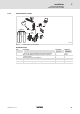
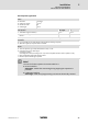
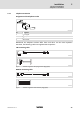
5.2.3 Communication via the diagnostic interface (9400)
2181FEW007
Fig. 5−4 Communication via the diagnostic interface (only 9400)
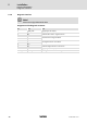
Installation steps
Step Action Connection
(see graphics)
Additional
information
1. Connect voltage supply to the plug connector 7 ^ 23
2. Connect diagnostic interface to the 9400 inverter (use
pre−assembled cable)
5 ^ 30
3. If it’s not possible to use the internal modem, connect an
external modem.
8 ^ 28
4. Connect inverter to CAN bus ; −
5. Connect ModemCAN 2181 to telephone network 4 ^ 29
We especially recommend carrying out communication via the diagnostic interface if the
2181 communication module is only connected temporarily.
In the case of a fixed installation, communication via CAN is preferable, see (¶ 21).