
Instruction Manual


Getting started
Parameterising drives via machine constants
Example for adapting a machine constant file
2
2.8
2.8.4
l
41
EDSTCXN EN 2.0
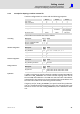
2.8.4 Example for adapting a machine constant file
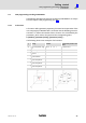
The drive configuration has 3 drives with the following properties:
Drive 1 Drive 2 Drive 3
Axis number 0 1 1
CAN node address 8 7 3
CAN baud rate 500 kB
Axis description c X (X’)
Axis type Rotation axis Linear axis with
handwheel
Gantry axis for
drive 2 with the
same properties
Resolution pulses 65536 65536 like drive 2
The machine constant file must look as follows:
MC keyword No. of
values
Values
MK_TEST_OHNEMECHANIK 1 0
MK_SPS_DUMMY 1 0
MC keyword No.of
values
Values
MK_CANDRIVES 12 −1, −1, 1, −1, −1, −1, 1, 0, −1, −1, −1, −1
MK_APPLACHSIDX 18 1, −1, −1, 0, −1, −1, −1, −1, −1, −1, −1, −1, −1, −1, −1, −1, −1,
−1
MK_ACHSENART 12 1, 192, 0, 0, 0, 0, 0, 0, 0, 0, 0, 0
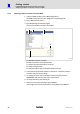
MC keyword No. of
values
Values
MK_CANOPEN_BAUDRATE 2 500, 1000
MC keyword No. of
values
Values
MK_IMPULSE 12 65536, 65536, 65536, 65536, 65536, 65536,
65536, 65536, 65536, 65536, 65536, 65536
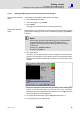
To define a synchronous axes, the same axis number is entered at 2 CAN note
addresses in MK_CANDRIVES. This creates a forced coupling of the axes of
the two CAN node addresses. The CAN axis with the lower node address
automatically is the master axis, the axis with the higher node address and
the same axis number is the slave axis (synchronous axis).
The gantry axis (X’, in MK_ACHSENART) is a special case of the synchronous
axes. It is a mechanical forced coupling of 2 axes. Thus, the gantry axis is not
entered as an axis of its own in MK_CANDRIVES, but as a reference to the X
axis.
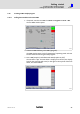
Test setting
Hardware configuration
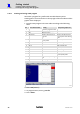
Software configuration
Setting of the axes
Explanation