
User guide


How to select your system cable
Blower cables
Extension cable
4
l
67
EDSYPFLD EN 8.0
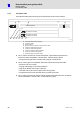
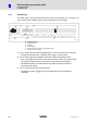
4.2.4 Extension cable
The table describes how to connect the blower to the control cabinet using a combination
of extension/connection cables.
EYL0001AxxxxL02A00
5 x 1.0
Extension cable Connecting cable
EYL0001VxxxxL04J04
EYL0001AxxxxL04A00
EYL0002AxxxxL02A00
EYL0002VxxxxL04J04
EYL0002AxxxxL04A00
12
45678 9
:
;< =
U
V
W
0 3
hb_tab_06
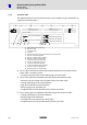
0 Forced−ventilated motor with plug
1 Extension cable
2 Connection cable
3 Control cabinet
4 Structure and cross−section of the extension/connection cable
5 Extension cable with SpeedTec
6 Extension cable for fixed installation
7 Extension cable as a trailing cable
8 Product key of the extension cable
9 Connection cable with screw plug
: Connection cable with SpeedTec
; Connection cable for fixed installation
< Connection cable as trailing cable
= Product key of the connection cable
ƒ The column contains the ’motor with blower’ symbol which represents the
consistent ’motor with blower − blower cables − control cabinet’ system.
– The symbol may represent a blower with a plug or a terminal box.
ƒ The column gives more detailed information about the extension cable:
– Structure and cross−section; this also holds for the connection cable
– Trailing cable design or for fixed installation
– Plug on the blower side or open cable end
– Always a plug on the control cabinet side
– The product key must be specified when you make your order.
ƒ The column gives more detailed information about the connection cable:
– Trailing cable design or for fixed installation
– Always a plug on the blower side
– The cable end on the control cabinet side is always open
– The product key must be specified when you make your order.