L-force Controls Ä.
L DMS 2.
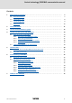
Control technology | PROFIBUS communication manual Contents 1 About this documentation . . . . . . . . . . . . . . . . . . . . . . . . . . . . . . . . . . . . . . . . . . . . . . . . . . . . . . . . . 5 1.1 Document history . . . . . . . . . . . . . . . . . . . . . . . . . . . . . . . . . . . . . . . . . . . . . . . . . . . . . . . . . . . . . . . 7 1.2 Conventions used . . . . . . . . . . . . . . . . . . . . . . . . . . . . . . . . . . . . . . . . . . . . . . . . . . . . . . . . . . . . . . .
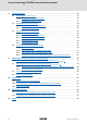
Control technology | PROFIBUS communication manual 8 9 10 11 12 4 Function libraries . . . . . . . . . . . . . . . . . . . . . . . . . . . . . . . . . . . . . . . . . . . . . . . . . . . . . . . . . . . . . . . . . 38 8.1 BusDiag.lib function library . . . . . . . . . . . . . . . . . . . . . . . . . . . . . . . . . . . . . . . . . . . . . . . . . . . . . . 8.1.1 DiagGetBusState function block . . . . . . . . . . . . . . . . . . . . . . . . . . . . . . . . . . . . . . . . . . 8.1.
Control technology | PROFIBUS communication manual About this documentation 1 About this documentation This documentation ... contains detailed information on how to commission, configure, and diagnose the PROFIBUS bus system within the Lenze control technology.
Control technology | PROFIBUS communication manual About this documentation Further technical documentations for Lenze components More information about Lenze components that can be used together with "PC-based automation" can be found in the following documents: Mounting & wiring Legend: MAs for Inverter Drives 8400 Printed documentation MAs for Servo Drives 9400 Online help/PDF MA EPM-Txxx (I/O system IP20) Abbreviations used: MA EPM-Sxxx (I/O system 1000) SHB System Manual MA 820
Control technology | PROFIBUS communication manual About this documentation Document history Target group This documentation is intended for all persons who plan, install, commission, and maintain the networking of devices in the field of control technology. 1.1 Document history Material no. Version Description 13294525 1.0 05/2009 TD17 First edition 13319345 2.0 10/2009 TD17 General revision 13369327 2.1 01/2011 TD17 Update for control technology release 2.5 13383678 2.
Control technology | PROFIBUS communication manual About this documentation Conventions used 1.2 Conventions used This documentation uses the following conventions to distinguish between different types of information: Type of information Highlighting Examples/notes Spelling of numbers Decimal separator Point The decimal point is always used. For example: 1234.56 Text Version information Program name Window Blue text colour »« The Message window... / The Options dialog box...
Control technology | PROFIBUS communication manual About this documentation Terminology used 1.3 Terminology used Term Meaning »Engineer« Lenze engineering tools supporting you during the entire life cycle of a machine - from the planning phase to maintenance. »Global Drive Control« / »GDC« »PLC Designer« Code "Container" for one or several parameters used for Lenze Servo Drives parameter setting or monitoring. Subcode If a code contains several parameters, they are stored in "subcodes".
Control technology | PROFIBUS communication manual About this documentation Notes used 1.
Control technology | PROFIBUS communication manual Safety instructions 2 Safety instructions Please observe the following safety instructions when you want to commission a controller or system using the industrial PC.
Control technology | PROFIBUS communication manual The "PC-based automation" system 3 The "PC-based automation" system Industrial PCs (IPCs) become more and more important in the field of automation technology. Due to their scaling options and various combinations of visualisation and control on one device, industrial PCs provide clear advantages for many applications.
Control technology | PROFIBUS communication manual The "PC-based automation" system Engineering tools for the engineering PC – The engineering PC communicates with the IPC via Ethernet. – Different engineering tools ( 22) serve to configure and parameterise the system. Fieldbuses Field devices DMS 2.
Control technology | PROFIBUS communication manual The Lenze control system with PROFIBUS Brief description of PROFIBUS 4 The Lenze control system with PROFIBUS Note! In the Lenze control system, only the PROFIBUS master functionality (logic bus) is supported. This chapter provides basic information about ... the PROFIBUS bus system in the Lenze control system; the structure of the Lenze control system with the PROFIBUS master; the components required for PROFIBUS communication. 4.
Control technology | PROFIBUS communication manual The Lenze control system with PROFIBUS Brief description of PROFIBUS 4.1.1 Structure of the PROFIBUS system Basic structure Physical structure The industrial PC (IPC) is the PROFIBUS master. It can communicate with one or several stations (slaves). PROFIBUS has an internal line topology (without repeater) or a tree topology (with repeater). Basic wiring of PROFIBUS ( 17) The PROFIBUS network must be terminated at the first and last station.
Control technology | PROFIBUS communication manual The Lenze control system with PROFIBUS Brief description of PROFIBUS Parameter setting The PROFIBUS stations can be parameterised in different ways: Direct access of the engineering software (from the engineering PC) to the slave field device.
Control technology | PROFIBUS communication manual The Lenze control system with PROFIBUS Brief description of PROFIBUS 4.1.2 Basic wiring of PROFIBUS The following examples show two simple PROFIBUS networks. Each segment of the network must be terminated at both ends. The bus terminators of PROFIBUS are marked with a "Z" in each of the following examples.
Control technology | PROFIBUS communication manual The Lenze control system with PROFIBUS Brief description of PROFIBUS 4.1.3 Combination with other bus systems The PROFIBUS bus system can be combined with CANopen. This makes sense if not all field devices are available for the same bus system or a motion bus (CANopen) is required in parallel to PROFIBUS (as logic bus). The bus systems are synchronised in the control system. 4.1.
Control technology | PROFIBUS communication manual The Lenze control system with PROFIBUS PROFIBUS hardware for the industrial PC 4.2 PROFIBUS hardware for the industrial PC MC-PBM communication card The MC-PBM communication card is a plug-in card for connecting an industrial PC as PROFIBUS master to a PROFIBUS network.
Control technology | PROFIBUS communication manual Technical data Technical data of the MC-PBM communication card 5 Technical data 5.1 Technical data of the MC-PBM communication card Field Values Protocol PROFIBUS-DP (V0, V1), ISO 7498 Communication medium RS485 Network topology Line terminated on both sides (without repeater) / tree (with repeater) • Termination with Sub-D plug Type within the network Master Max. number of stations per segment 63 Max.
Control technology | PROFIBUS communication manual Technical data Bus cable specification 5.2 Bus cable specification Please follow the specifications of the PROFIBUS user organisation for bus cables. Field Values Cable resistance 135 ... 165 Ω/km, (f = 3 ... 20 MHz) Capacitance per unit length ≤ 30 nF/km Loop resistance < 110 Ω/km Core diameter > 0.64 mm Core cross-section > 0.
Control technology | PROFIBUS communication manual Commissioning of PROFIBUS Overview of the commissioning steps 6 Commissioning of PROFIBUS This chapter provides information about how to commission the Lenze control system with PROFIBUS. Depending on the field devices used, the following Lenze engineering tools are required: »PLC Designer« »Engineer« »Global Drive Control« (GDC) Tip! For using other fieldbus systems, you may require further engineering software.
Control technology | PROFIBUS communication manual Commissioning of PROFIBUS Detailed commissioning steps 6.2 Detailed commissioning steps The individual commissioning steps are described in the following sections. Follow the instructions step by step to commission your system. 6.2.1 More detailed information about how to work with the Lenze engineering tools can be found in the corresponding manuals and online helps.
Control technology | PROFIBUS communication manual Commissioning of PROFIBUS Detailed commissioning steps 6.2.3 Creating a project folder Create a project folder on the engineering PC.
Control technology | PROFIBUS communication manual Commissioning of PROFIBUS Detailed commissioning steps 6.2.5 Commissioning of field devices Parameterise the Lenze field devices connected to PROFIBUS either with the »Engineer« or with »GDC«, depending on the device. PROFIBUS is exclusively configured with the »PLC Designer«. Observe the information with regard to commissioning in the documentation for the field devices.
Control technology | PROFIBUS communication manual Commissioning of PROFIBUS Detailed commissioning steps 6.2.6 Configuration in the »PLC Designer« The »PLC Designer« serves to map the field device topology in the control configuration. Tip! The »PLC Designer« serves to configure PROFIBUS stations and nodes on other fieldbus systems. CANopen with PROFIBUS ( 37) 6.2.6.1 Creating a PLC program How to create a PLC program in the »PLC Designer«: 1.
Control technology | PROFIBUS communication manual Commissioning of PROFIBUS Detailed commissioning steps 4. Create a block: DMS 2.2 EN 07/2011 TD17 Note! The block must contain at least one instruction to function properly.
Control technology | PROFIBUS communication manual Commissioning of PROFIBUS Detailed commissioning steps 5. Create the control configuration: • Open the Resources dialog box: • Open the PLC Configuration dialog box: Setting Description Automatic calculation of addresses Every newly added module automatically gets an address which results from the address of the module integrated before and the size of this module.
Control technology | PROFIBUS communication manual Commissioning of PROFIBUS Detailed commissioning steps 6.2.6.2 Configuring the PROFIBUS master How to configure the PROFIBUS master: 1. Add the bus interface to the PLC configuration: The "ProfibusMaster" subelement represents the PROFIBUS interface of the IPC to which the logic bus is connected. 2. Set DP parameters for the PROFIBUS master: • The standard setting of the PROFIBUS master station address is ’1’.
Control technology | PROFIBUS communication manual Commissioning of PROFIBUS Detailed commissioning steps Up to eight groups can be arranged. Set for each group whether they are to be operated in freeze mode and/or sync mode. By assigning the slaves (see "Properties of the DP slave", "Group assignment") to different groups, the data exchange from the master via a global control command can be synchronised.
Control technology | PROFIBUS communication manual Commissioning of PROFIBUS Detailed commissioning steps 3. Go to the Bus parameters tab to set the baud rate for PROFIBUS: 4. Go to the Module parameters tab to set the "Byteorder wordmodules motorola" parameter: The "Byteorder wordmodules motorola" parameter determines how the data are copied from PROFIBUS to the process image.
Control technology | PROFIBUS communication manual Commissioning of PROFIBUS Detailed commissioning steps 5. Attach PROFIBUS slave: The GSE file of the PROFIBUS slave must be stored in the »PLC Designer« target directory. Storing the device data base files (GSE) ( 24) 32 L DMS 2.
Control technology | PROFIBUS communication manual Commissioning of PROFIBUS Detailed commissioning steps 6.2.6.3 Configuring the PROFIBUS slave How to configure the PROFIBUS slave: 1. Set DP parameters for the PROFIBUS slave: • Enter the station address of the PROFIBUS slave here. • A baud rate does not need to be set since the slave recognises the baud rate automatically. • The GSE file... button serves to open and inspect the device-related GSE file. DMS 2.
Control technology | PROFIBUS communication manual Commissioning of PROFIBUS Detailed commissioning steps 2. Via the Input/Output tab, configure the input and output objects for the slaves. Note! The input and output objects must be configured in the same sequence as they are arranged physically at the bus. • In the left window, the dialog lists all input and output modules, process data objects (PCD) and DRIVECOM parameter objects (e.g.
Control technology | PROFIBUS communication manual Commissioning of PROFIBUS Detailed commissioning steps 3. Assign for each address of the input and output objects (e.g. %IB0, %QB0, ...) a symbolic name which is non-ambiguous in the entire control configuration in accordance with the IEC 61131 syntax (no blanks and leading digits in the variable name): • Symbolic names can be entered by a mouse-click in front of ’AT %... ;’.
Control technology | PROFIBUS communication manual Commissioning of PROFIBUS Detailed commissioning steps 6.2.6.4 Compiling project data To compile the project data, select the ProjectBuild menu command or press the function key. If errors occurred during the compilation process, you can locate and eliminate them by means of the »PLC Designer« error messages. Then compile the project data again.
Control technology | PROFIBUS communication manual CANopen with PROFIBUS 7 CANopen with PROFIBUS The PROFIBUS bus system can be combined with CANopen. This makes sense if not all field devices are available for the same bus system or a motion bus (CANopen) is required in parallel to PROFIBUS (as logic bus). The bus systems are synchronised in the control system.
Control technology | PROFIBUS communication manual Function libraries 8 Function libraries For configuring PROFIBUS and for diagnostic purposes, the following function libraries are available in the »PLC Designer«: Function libraries Application BusDiag.lib function library ( 39) This library serves to query diagnostics information from the PROFIBUS master and the slaves. NetXPBInfo.lib function library ( 44) This library serves to query various information of the PROFIBUS master (e.g.
Control technology | PROFIBUS communication manual Function libraries BusDiag.lib function library 8.1 BusDiag.lib function library The BusDiag.lib function library contains the following function blocks for diagnostics: DiagGetBusState function block ( 39) DiagGetState function block ( 41) 8.1.1 DiagGetBusState function block This block serves to display the current bus status. DiagGetBusState must be set via AT %MByy to the diagnostics address of the PROFIBUS station to be diagnosed.
Control technology | PROFIBUS communication manual Function libraries BusDiag.lib function library Inputs (VAR_INPUT) The status is updated in the background. Thus, the input variables do not need to be preassigned. Identifier/data type ENABLE Meaning/possible settings The function block is activated in an edge-controlled manner: BOOL • Positive edge (TRUE) = diagnostics information is detected and READY is set to TRUE.
Control technology | PROFIBUS communication manual Function libraries BusDiag.lib function library 8.1.2 DiagGetState function block If a station available on the bus reports an error, its specific diagnostics information can be read with the DiagGetState block. DiagGetState must be called explicitly with the device number and the bus member ID (station address).
Control technology | PROFIBUS communication manual Function libraries BusDiag.lib function library Identifier/data type Meaning/possible settings Contains the slave-specific diagnostics information. EXTENDEDINFO ARRAY [0...129] Byte 0 Station status 1 OF BYTE Byte 1 Station status 2 Byte 2 Station status 3 Byte 3 Master station number Byte 4 Manufacturer's identification mark (high byte) Byte 5 Manufacturer's identification mark (low byte) Byte 6 ...
Control technology | PROFIBUS communication manual Function libraries BusDiag.lib function library Byte in EXTENDEDINFO Meaning 18 ... 21 Error code of the PROFIBUS station • More information can be found in the documentation of the corresponding PROFIBUS station. DMS 2.
Control technology | PROFIBUS communication manual Function libraries NetXPBInfo.lib function library 8.2 NetXPBInfo.lib function library The NetXPBInfo.lib function library serves to query various information on the PROFIBUS master (e.g. error counter, bus cycle counter). 8.2.
Control technology | PROFIBUS communication manual Function libraries NetXPBInfo.lib function library 8.2.2 NetXGetPBInfos function This function serves to request various information on the NetX PROFIBUS master. The information is entered into the memory transferred. The return value contains the error code. ’0’ indicates an error, a value unequal ’0’ indicates a successful query.
Control technology | PROFIBUS communication manual Function libraries HilscherNetX.lib function library 8.3 HilscherNetX.lib function library The HilscherNetX.lib function library enables direct access to the package interface of the PROFIBUS communication card. 8.3.1 In order to use the functions of the library, you must be provided with the corresponding documentation of the respective NetX Hilscher firmware. The documentation can be procured from the Lenze service.
Control technology | PROFIBUS communication manual Function libraries HilscherNetX.lib function library 8.3.
Control technology | PROFIBUS communication manual Function libraries HilscherNetX.lib function library 8.3.3 CIFXGetChannelHandle function This function provides the handle of the NetX channel as return value. This handle can be used to request the CIFXGetPacket functions and CIFXPutPacket. In the event of an error, ’0’ is returned. Inputs (VAR_INPUT) Identifier/data type Meaning/possible settings iDevice 8.3.
Control technology | PROFIBUS communication manual Function libraries HilscherNetX.lib function library 8.3.5 CIFXGetPacket function This function retrieves the response to a package transmitted before. For this, the management data of the transmitted package must be accepted unchanged. It is important that the ulSrcId value changed by the driver is transferred. The return value is the error code. ’0’ means error-free, unequal ’0’ is the error case.
Control technology | PROFIBUS communication manual Function libraries SysLibDPV1Hilscher.lib function library 8.4 SysLibDPV1Hilscher.lib function library The SysLibDPV1Hilscher.lib function library supports the acyclic PROFIBUS DPV1 - class 1 write and read services for data transfer between the master and the slaves. The data is addressed within the slave stations via slot and index (for this see the PROFIBUS-DP standard).
Control technology | PROFIBUS communication manual Function libraries SysLibDPV1Hilscher.lib function library 8.4.2 DPV1_Read / DPV1_ReadEx function block This function block serves to read data. Inputs (VAR_INPUT) Identifier/data type ENABLE Meaning/possible settings The function block is activated in an edge-controlled manner: BOOL • Positive edge (TRUE) = diagnostics information is detected and READY is set to TRUE.
Control technology | PROFIBUS communication manual Function libraries SysLibDPV1Hilscher.lib function library 8.4.3 DPV1_Write / DPV1_WriteEx function block This function block serves to write data. Inputs (VAR_INPUT) Identifier/data type ENABLE Meaning/possible settings The function block is activated in an edge-controlled manner: BOOL • Positive edge (TRUE) = diagnostics information is detected and READY is set to TRUE.
Control technology | PROFIBUS communication manual Function libraries SysLibDPV1Hilscher.lib function library 8.4.4 Telegram examples of the PROFIdrive parameter data channel (DP-V1) In the following, a parameter read order and a parameter write order for a Servo Drive 9400 are described. 8.4.4.1 Example of read request: Query heatsink temperature The heatsink temperature of the Servo Drive 9400 is to be read.
Control technology | PROFIBUS communication manual Function libraries SysLibDPV1Hilscher.lib function library Parameter response to a read error Byte 1 Byte 2 Byte 3 Byte 4 Job reference Response identification Axis Number of indexes 0x01 0xXX 0x81 0x00 (Mirrored) Parameter not read (Mirrored) Byte 5 Byte 6 Format Number of values 0x44 0x01 Error Error code without additional information Byte 7 Byte 8 Error code High byte Low byte See documentation of the PROFIBUS station.
Control technology | PROFIBUS communication manual Function libraries SysLibDPV1Hilscher.lib function library 8.4.4.2 Example of write request: Set deceleration time for quick stop In the Servo Drive 9400, the ramp time for quick stop is to be set to 50 ms.
Control technology | PROFIBUS communication manual Function libraries SysLibDPV1Hilscher.
Control technology | PROFIBUS communication manual Defining the minimum cycle time of the PLC project Calculating the total access time to the peripheral devices (TCorrection) 9 Defining the minimum cycle time of the PLC project This chapter will inform you on how the minimum cycle time of the PLC project can be defined. The calculation of the minimum cycle time comprises the following steps: 1. Calculating the total access time TCorrection to the peripheral devices.
Control technology | PROFIBUS communication manual Defining the minimum cycle time of the PLC project Detecting the task utilisation of the application (TTask utilisation) 9.2 Detecting the task utilisation of the application (TTask utilisation) The time TTask utilisation cannot be calculated. It is determined in the running system. For this the system is commissioned on the basis of cycle times that are sufficiently long, and afterwards it is optimised.
Control technology | PROFIBUS communication manual Defining the minimum cycle time of the PLC project Detecting the task utilisation of the application (TTask utilisation) 9.2.2 Detecting the task utilisation Initial situation A project with, for instance, a motion task and two 2 tasks of a lower priority is created completely. How to detect the task utilisation TTask utilisation: 1. For a first measurement of TTask utilisation the cycle times of all cyclic tasks in the PLC system are set to 'long'.
Control technology | PROFIBUS communication manual Defining the minimum cycle time of the PLC project Calculating the minimum cycle time 9.3 Calculating the minimum cycle time Note! For calculating the minimum cycle time, a safety factor of 1.5 is included. The minimum cycle time Tmin for a system results from the sum of the times detected before, multiplied by the safety factor: Tmin > safety factor x ( TTask utilisation + TCorrection ) Example Configuration: Industrial PC (ATOM 1.
Control technology | PROFIBUS communication manual Defining the minimum cycle time of the PLC project Optimising the system 9.4 Optimising the system How to optimise the system: 1. Log in and load project. 2. Check the task processing times. 3. Optimising the cycle times: • If required technologically, the cycle times of the remaining tasks with lower priorities can be decreased.
Control technology | PROFIBUS communication manual Diagnostics Diagnostics in the »PLC Designer« 10 Diagnostics PROFIBUS can be diagnosed in the »PLC Designer« by means of specific diagnostics function blocks. Moreover, the field devices, PROFIBUS communication modules, and the MC-PBM communication card are provided with LED status displays for diagnostics. 10.1 Diagnostics in the »PLC Designer« For the diagnostics of PROFIBUS in the »PLC Designer«, the BusDiag.
Control technology | PROFIBUS communication manual Diagnostics LED status displays 10.3 LED status displays The LED status displays of the field devices, PROFIBUS communication modules, and the MC-PBM communication card provide information on the device and communication states. Detailed information on the LED status displays of the field devices and PROFIBUS communication modules can be found in the corresponding documentation.
Control technology | PROFIBUS communication manual Parameter reference 11 Parameter reference This chapter supplements the parameter list provided in the online documentation for the industrial PC by the parameters of the MC-PBM communication card: Parameters of the MC-PBM communication card in slot 1 ( 65) Parameters of the MC-PBM communication card in slot 2 ( 66) Note! • Several MC_PBM communication cards can be used per industrial PC. The name of the card in the »WebConfig« is MC-PBM.
Control technology | PROFIBUS communication manual Parameter reference Parameters of the MC-PBM communication card in slot 1 11.1 Parameters of the MC-PBM communication card in slot 1 The parameters are listed in numerically ascending order.
Control technology | PROFIBUS communication manual Parameter reference Parameters of the MC-PBM communication card in slot 2 11.2 Parameters of the MC-PBM communication card in slot 2 The parameters are listed in numerically ascending order.
Control technology | PROFIBUS communication manual Index 12 Index A Addressing the CANopen and PROFIBUS stations 37 Application notes (representation) 10 B Baud rate 21 Brief description of PROFIBUS 14 Bus cable length 21 Bus terminating resistor 23 BusDiag.lib 39 BusDiag.
Control technology | PROFIBUS communication manual Index H T HilscherNetX.lib 46 HilscherNetX.
© 07/2011 ) Lenze Automation GmbH Grünstraße 36 D-40667 Meerbusch Germany Service +49 (0)21 32 / 99 04-0 Lenze Service GmbH Breslauer Straße 3 D-32699 Extertal Germany 00 80 00 / 24 4 68 77 (24 h helpline) ¬ +49 (0)21 32 / 7 21 90 ¬ +49 (0)51 54 / 82-11 12 | Lenze@Lenze.de | Service@Lenze.de Þ www.Lenze.com KHBPBPCBAUTO 13383678 EN 2.