Show/Hide Bookmarks BA 11.
Show/Hide Bookmarks What is new / what has changed ? Material No. 00 178 416 00 390 299 Edition 1.0 06/94 TD09 1.0 01/96 TD09 00 390 299 2.0 07/97 TD09 00 453 985 1.0 05/02 TD09 Important 1st edition 1st edition Replaces 178 415 2nd edition Replaces 1st edition 1st edition Replaces 390 299 Contents First edition for pilot series Completely revised Product key completed Chapter 3.3.2 Ambient media: new Chapter 6.4 Spare parts new Chapter 3.1.2: Item numbers of spare parts list adapted Chapter 6.
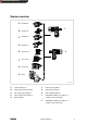
Show/Hide Bookmarks System overview 12.600.LL 12.601.LL & 12.602.LL ! 12.603.LL " 52.154.LL # 52.116.LL $ 12.503.LL % GLL ' K11.0311/1 Helical gearbox i=1 Single-stage helical gearbox Two-stage helical gearbox ! " Three-stage helical gearbox # $ % & Worm gearbox Helical worm gearbox Helical bevel gearbox Series GLL gearboxes Simplabelt variable speed drive for compact units in U-design ' Simplabelt variable speed drive for compact units in Z-design l BA S’belt KE EN 1.
Show/Hide Bookmarks Type code ! 11. 432 . 20 . 16 . 2 " # Type 11.
Show/Hide Bookmarks Product key Gearbox type Gearbox size Number of stages Input design K Drive size Compact Units Output design Shaft GS T Helical gearbox G F L Low-profile gearbox GK S Output Solid shaft V R without flange Helical-bevel gearbox Hollow shaft H K with flange (trough-holes) Bevel gearbox Hollow shaft with shrink disk S L with flange (threaded-holes) G KR GS S Helical-worm gearbox Housing with pitch circle * A with centering and foot B with foot (without cen
Show/Hide Bookmarks Contents 1 Preface and general information . . . . . . . . . . . . . . . . . . . . . . . . . . . . . . . . . . . . . . . . . . . 8 1.1 How to use these Operating Instructions . . . . . . . . . . . . . . . . . . . . . . . . . . . . . . . . . . . . . . . . . . . . . . . . 1.1.1 Terminology used . . . . . . . . . . . . . . . . . . . . . . . . . . . . . . . . . . . . . . . . . . . . . . . . . . . . . . . . . 8 8 1.2 Contents of delivery . . . . . . . . . . . . . . . . . . . . . . . .
Show/Hide Bookmarks Contents 6 Maintenance . . . . . . . . . . . . . . . . . . . . . . . . . . . . . . . . . . . . . . . . . . . . . . . . . . . . . . . . . . 20 6.1 Maintenance intervals . . . . . . . . . . . . . . . . . . . . . . . . . . . . . . . . . . . . . . . . . . . . . . . . . . . . . . . . . . . . . 20 6.2 Maintenance operations . . . . . . . . . . . . . . . . . . . . . . . . . . . . . . . . . . . . . . . . . . . . . . . . . . . . . . . . . . . . 6.2.1 Replacing the V-belt . . . . . . . . .
Show/Hide Bookmarks Preface and general information 1 Preface and general information 1.1 How to use these Operating Instructions 1.1.1 l These operating instructions are intended for safety-relevant operations on and with the Simplabelt compact units. They contain safety information which must be observed. l All personnel working on and with the compact units must have the Operating Instructions available and observe the information and notes which are relevant for them.
Show/Hide Bookmarks Preface and general information 1.3 Lenze-drive systems 1.3.1 Labelling 1.3.2 l Lenze drive systems are uniquely designated by the content of their nameplates.
Show/Hide Bookmarks Safety information 2 Safety information 2.1 Personnel responsible for safety Operator l An operator is any natural or legal person who uses the drive system or on behalf of whom the drive system is used. l The operator or his safety officer must ensure – that all relevant regulations, instructions and legislation are observed. – that only qualified personnel works with and on the drive system.
Show/Hide Bookmarks Safety information 2.3 Layout of the safety information l All safety information in these operating instructions has a uniform design: Signalwort! Hinweistext – The icon designates the kind of danger. – The signal word designates the severeness of the danger. – The notes describe the danger and suggest how to avoid the danger.
Show/Hide Bookmarks Technical data 3 Technical data l The most important data are indicated on the nameplate. l Further technical data are listed in the product catalogues. 3.1 Product features 3.1.1 Design Drive systems have a modular design. They consist of: 3.1.
Show/Hide Bookmarks Technical data 2 11BA 1.16 1.15 1BA 6BA 7BA 8BA 1 3BA 12BA 2BA 4BA 5BA K11.0365/1 Fig. 1 Simplabelt compact unit, U-design 8BA 7BA 6BA 1BA 1.15 1.16 11BA 2 1 3BA 4BA 5BA 2BA 12BA K11.0365/1 Fig. 2 L Simplabelt compact unit, Z-design BA S’belt KE EN 1.
Show/Hide Bookmarks Technical data 3.2 Weights Compact Units Weight [kg] 11.4L1.10 11.4L2.10 11.4L3.10 11.4L5.10 < < < < 25 25 40 25 11.4L1.13 11.4L2.13 11.4L3.13 11.4L5.13 11.4L6.13 11.4L7.13 11.4L1.16 11.4L2.16 11.4L3.16 11.4L5.16 11.4L6.16 11.4L7.16 11.4L1.20 11.4L2.20 11.4L3.20 11.4L5.20 11.4L6.20 11.4L7.20 < 60 < 60 < 80 < 60 < 60 <60 < 100 < 100 < 125 < 100 < 100 <125 < 100 < 125 < 250 < 150 < 150 < 200 3.3 Operating conditions 3.3.1 Temperatures Compact Units Weight [kg] 11.431.25 11.
Show/Hide Bookmarks Installation 4 Installation Caution! Transport the drive only with transport equipment or hoists which are suitable for this load. Ensure a safe fixing. Avoid shocks! The units in Z-design are not stable! Ensure proper support! 4.1 Storage If you do not install the gearbox immediately, ensure the appropriate storage conditions. l Up to one year: Without special measures in dry, dust-free rooms which are protected against sunlight.
Show/Hide Bookmarks Installation Stop! The lubricant filling is adapted to the mounting position. To avoid damages to the gearbox, do not change the mounting position indicated on the nameplate. Caution! Compact units in Z-design are not stable. Ensure propper support. 4.3 Electrical connection Danger! Electrical connections must only be carried out by skilled personnel! 4.3.
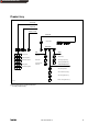
Show/Hide Bookmarks Installation F1 Fuse K1, K2 Combined contactor relay for phase reversion (CW or CCW rotation of the adjusting motor) M1 Q1 Remote-control motor Main switch Q2 Motor circuit breaker S1 Momentary-contact switch “faster” S2 Momentary-contact switch “slower” S3 S4 Limit switch (highest speed limit) Limit speed (lowest speed limit) ① ② ③ ④ Drive motor ① ② ③ Control phase of drive motor faster ④ slower K11.0252 Fig.
Show/Hide Bookmarks Installation Fig. 5 Output voltage of the three-phase AC tacho with rectification as a function of the speed and the input resistance of the display unit Pulse recorder The contactless speed measuring works with a rotating punched disk and a fixed pulse recorder. In connection with a NAMUR input the pulse recorder generates a digital signal. Suitable Lenze display units: Analog voltmeter VSC 96 (approx.
Show/Hide Bookmarks Commissioning 5 Commissioning and operation Stop! The drive must only be commissioned by skilled personnel! 5.1 Before you start Ensure that the drive is not connected to mains and does not rotate unintentionally. Please check: 5.2 l Is the mechnical fixing o.k.? l Are the electrical connections o.k.
Show/Hide Bookmarks Maintenance 6 Maintenance 6.1 Maintenance intervals Stop! With drive systems: Please observe the maintenance intervals of the other drive components, too! l Wide V-belts have a natural wear which depends on several factors: – On-time – Load type – Speeds – Ambient temperature As a guide value Lenze recommends to check the wide V-belt for wear and fissures every 4 to 6 months and replace it, if necessary. l Variable speed pulleys are maintenance-free.
Show/Hide Bookmarks Maintenance Disassembly with Z-design (see Fig. 2): 1. Activate the drive and accelerate it to max. speed, then switch off the drive and disconnect it from the mains. 2. Loosen 6 screws (1.16; 1.15). Then push aside the covers (5BA and 4BA) to remove the V-belt (3BA) from the variable speed pulley (1BA). The three-phase AC motor (5.0) must be supported.
Show/Hide Bookmarks Maintenance 6.2.3 Replacing the lubricant at gearboxes See Gearbox Operating Instructions. Stop! Never adjust the speed at standstill! Otherwise, the compact unit will be damaged! It must be observed that the V-belt l does not run on the hub base (clearly audible running noises). l does not run over the edge of the variable speed pulley. Non-observance may lead to damage of the drive (bearing damage, belt damage). Procedure of electric remote adjustment (Fig. 3) 1.
Show/Hide Bookmarks Maintenance 4 5 6 7 8 9 Cover Fixing screw Bolt Setscrew Handwheel Position indicator K 11.0263 Fig. 8 Front adjustment 4 5 6 7 8 9 Cover Fixing screw Bolt Setscrew Handwheel Position indicator 0 drawing turned by 90° K 11.0263/2 Fig. 9 Angle adjustment 6.3 Repair Lenze recommends that repairs are carried out by Lenze Service. L BA S’belt KE EN 1.
Show/Hide Bookmarks 24 6.4 Spare-parts list 1BA 6BA BA S’belt KE EN 1.0 3BA 7BA 8BA 9BA 10BA 12BA L Fig.
Show/Hide Bookmarks L 6.5 Order form Recipient: Lenze Postal code/City:___________________ Fax-no.: ___________________ all GLL Sender BA S’belt KE EN 1.0 Company __________________________ Customer no. __________________ Street / P.O. Box __________________________ Order no.
Show/Hide Bookmarks Troubleshooting and fault elimination 7 Troubleshooting and fault elimination If any disturbance should occur during operation of the drive system, please check the possible causes using the following table. If the fault cannot be eliminated by means of one of the listed measures, please contact Lenze Service.
Show/Hide Bookmarks Waste disposal 8 Waste disposal Help to protect the environment! Packing material can be recycled.
Show/Hide Bookmarks Manufacturer’s Certification Manufacturer’s Certification Gearboxes We herewith certify that the below listed products are intended for assembly into a machine or for assembly with other elements to form a machine. Commissioning of the machine is prohibited before it is proven that it corresponds to the EC regulation 98/37/EC.
Show/Hide Bookmarks Notes L BA S’belt KE EN 1.
Show/Hide Bookmarks Notes 30 BA S’belt KE EN 1.