smd Series Drives Modbus Communications Reference Guide
About These Instructions This documentation applies to the use of an smd Series Variable Frequency Drive in a Modbus Network and should be used in conjunction with the smd Series Operating Instructions (Document SL03) that shipped with the drive. These documents should be read in their entirety as they contain important technical data and describe the installation and operation of the drive. Modbus® and Modicon® are registered trademarks of Schneider Electric; http://www.schneider-electric.com.
Contents 1 Safety Information..............................................................................................................1 1.1 1.2 2 3 4 Warnings, Cautions and Notes...............................................................................1 1.1.1 General.....................................................................................................1 1.1.2 Application................................................................................................1 1.1.
Contents 5 6 7 smd Drive Control Registers...............................................................................................12 5.1 Abbreviations.........................................................................................................13 5.2 Drive Control - Register #1....................................................................................13 5.3 Drive Hardware Configuration - Register #22.........................................................14 5.
Safety Information 1 Safety Information 1.1 Warnings, Cautions and Notes 1.1.1 General Some parts of Lenze controllers (frequency inverters, servo inverters, DC controllers) can be live, moving and rotating. Some surfaces can be hot. Non-authorized removal of the required cover, inappropriate use, and incorrect installation or operation creates the risk of severe injury to personnel or damage to equipment.
Safety Information 1.1.4 Electrical Connection When working on live drive controllers, applicable national regulations for the prevention of accidents (e.g. VBG 4) must be observed. The electrical installation must be carried out in accordance with the appropriate regulations (e.g. cable cross-sections, fuses, PE connection). Additional information can be obtained from the regulatory documentation.
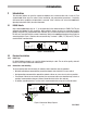
Introduction 2 Introduction This document defines the specifics required for Modbus serial communication with a Lenze-AC Tech standard smd Series drive for control, status monitoring, and programming parameters. A familiarity with normal drive capabilities and operations is assumed. If this is not the case, refer to the smd Series Operating Instructions (SL03) for more information. 2.1 RS485 Details Only standard smd models with an “L” as the eighth digit in the model number (ex.
Introduction 2.2.3 Network Termination For an RS-485 network it is essential to install the specified termination resistors (120W), i.e. one at both ends of a network segment. Failure to do so will result in signals being reflected back along the cable which will cause data corruption. An external 120W 1/4W resistor can be connected as shown in Figure 3.
Introduction D. The function codes supported by the smd drives are: 03 Read Holding Register (4X references). In general we can read only one register at a time. However, there are a few limited exceptions. Exception One: Register #24 (Modbus Register #25) Drive Status, can also be read as a group of 6 words. Exception Two: Parameter C99 (Software Version) is a 4-word read. 04 Read Input Register (3X references). As with function 03, we read one register at a time except where noted.
Introduction 2.4 Universal Registers Lenze-AC Tech manufactures several drive families. Currently the QC, MC, MCH, SC, TC, smd, Tmd and SMV Series drives support Modbus based communications. Since each drive family has different parameters and size ranges, the parameter (register) definitions are in many cases quite different. In order to facilitate communication in a network with a mix of drive types, certain Lenze-AC Tech Register locations have been made universal among Lenze-AC Tech drives.
Data & Register Format 3 Data Representation - Internal and External 3.1 Register Format All registers are 16 bits. The data within these registers can take on the following forms: • Individual bit commands (16 per register). Example: Register #1 (Modbus Register #2). • Individual bit flags (16 per register). Example: Register #22. • A chain of two 8 bit unsigned integers. • A 16 bit unsigned integer.
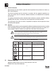
Drive Setup & Operation 4 smd Drive Setup & Operation 4.1 Control Parameter In order to communicate using Modbus protocol, the smd Control Source Setpoint (parameter #C01) must be set to one of the selections listed in Table 4. Table 4: Control Source Setpoint C01 (Register 51) Setting Source Program Control (Monitoring) 4.
Drive Setup & Operation 4.4 Watchdog Timer The smd drive is equipped with a Serial Link “Watchdog Timer”. If the Modbus Master wishes to control the drive (start, stop, forward, reverse, etc.) it must first “Unlock Controls” (section 4.4). If the Watchdog Timer is enabled and controls have been unlocked, the Master MUST PERIODICALLY COMMUNICATE with the drive or the timer will timeout. Communications should typically be done at less than 1/2 the interval specified in n23, Serial Fault Time.
Drive Setup & Operation 4.5 Unlocking & Locking Controls Registers #48 and #1 are used in Unlocking and Locking Controls. • A write to Register #48 (Unlock Controls) with a value of 0 will unlock controls. This enables the writing of Register #1 – the Drive Control Register and register #40 (keypad speed command). Note: C01 must be set to either 10 or 11 in order to unlock serial control. 4.
Drive Setup & Operation 4.8 Normal Control Operation Sequence 1. Power up drive. 2. Set parameter C01 (Control Source Setpoint) to selection 10 or 11. 3. Close terminal 28. 4. Unlock control by writing a zero to Register #48. 5. Control drive operation via various commands to Register #1 (Start, Stop, Reverse direction, etc.). 6. Set the network speed reference by setting bit 8 of Register #1.
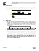
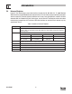
Drive Control & Communication 5 smd Drive Control Registers Table 6 describes the smd Drive Control Registers in ascending order of smd Register #. The HEX representation is given in parenthesis next to the smd Register # in the left-most column. REGISTER NAME 1 (01) Drive Control 19 (13) Drive Family 21 (15) Drive Size 22 (16) Drive H/W 24 (18) Drive Status (6 register read) (reg. #24 to 29) 24 (18) Command Speed 25 (19) Actual Speed 26 (1A) Load (DH) / Status (DL) 27 (1B) Act.
Drive Control & Communication 5.
Drive Control & Communication NOTE 1 - Drive Control • • • During each write to Register #1 only one bit should be set in the drive control word. If more than 1 bit is set, the drive responds to stop bit only. If stop bit is not set, but more than 1 bit is set, drive responds with exception 04.
Drive Control & Communication 5.4 Drive Status - Registers #24-29 5.4.1 Reading Register #24 When reading register #24, the group of words requested can be either 1 or 6. This is an exception to the rule of being able to read only one register at a time.
Drive Control & Communication 5.4.2 Operational Status - Register #26 Table 11 lists the Operational Status (Register #24 byte D3L or Register #26 DL) Table 11: Operational Status Bit 0 1 2 3 4 5 6 7 8 9 10 11 12 13 5.4.
Drive Control & Communication 5.4.5 Speed Command Source - Registers #24 & 28 Table 14 lists the Speed Command Source (Register #24 byte D5H or Register #28 DH). Table 14: Speed Command Source 5.4.6 Setting Source 0 ANALOG FREQ. 1 PRESET c40 2 PRESET 1 3 PRESET 2 4 PRESET 3 5 MOP SPEED 6 SERIAL SPEED Speed Reference Status - Registers #24 & 28 Table 15 lists the Speed Reference Status (Register #24 byte D5L or Register #28 DL). Table 15: Speed Reference 5.4.
Drive Control & Communication 5.4.8 Commanded Rotational Direction - Registers #24 & 29 Table 17 lists the Commanded Rotational Direction (Register #24 byte D6L or Register #29 DL) Table 17: Commanded Rotational Direction 5.5 Setting Direction 0 FORWARD 1 REVERSE Motor Volts - Register #30 Output Voltage to the motor expressed as a percentage of nominal drive voltage. 5.6 Serial Speed - Register #40 This register enables the user to set the serial speed to desired value. 5.
Drive Control & Communication 6 smd Programming Parameters 6.1 Format NOTE - Attention Parameter list presented in Section 6.2 is valid only for smd parameter version 400 and 507. For revisions, refer to appropriate smd Manual.
Drive Control & Communication Parameter No. 1 6.
Parameter No.
Parameter No. 1 Drive Control & Communication smd Register # (hexadecimal representation) Parameter Name Range of Adjustment 2, Modbus value (decimal value) Factory Default PV400 PV507 C38 74 (4AH) 75 (4BH) Fixed Setpoint 2 (JOG2) 0 - 9990 (0.0 - 999) 30.0 Hz C39 75 (4BH) 76 (4CH) Fixed Setpoint 3 (JOG3) 0 - 9990 (0.0 - 999) 40.0 Hz C46 78 (4EH) 79 (4FH) Frequency Setpoint 0 - 2400 (0.0 - 240 Hz) Read Only C50 79 (4FH) 80 (50H) Output Frequency 0 - 2400 (0.
Parameter No. 1 Drive Control & Communication c25 smd Register # (hexadecimal representation) Parameter Name Range of Adjustment 2, Modbus value (decimal value) PV400 PV507 95 (5FH) 103 (67H) LECOM Baud Rate 0 1 2 3 105 (69H) PI Actual Setpoint c86 - c87 c38 9600 bps (9600, 8, N, 2 4800 bps (9600, 8, N, 1 2400 bps (9600, 8, E, 1 1200 bps (9600, 8, O, 1 if C01 = 8...11) if C01 = 8...11) if C01 = 8...11) if C01 = 8...11) Factory Default 0 Read Only c40 97 (61H) 106 (6AH) Freq.
Drive Control & Communication NOTE 5 - smd - Fault History Parameters c61 (Present Fault), c62 (Last Fault) and c63 (Last but one Fault) provide the Fault History for the smd drive. Table 18 lists the fault codes.
Drive Control & Communication 7 Quick Start Instructions Follow these Quick Start instructions to use Modbus Communications for basic network control of an smd drive. These instructions are for basic start, stop, direction and speed control of the smd drive. To download the smd manual visit the Lenze-AC Tech Technical Library at http://www.lenze-actech.com. 7.1 Initial Settings These instructions are for basic start, stop direction and speed control of the smd drive using Modbus communication. 1.
Drive Control & Communication 7.2 Drive Control 1. Please be advised that while the drive is under network control the local STOP circuit is always enabled. Input 28 needs to be asserted in order for the drive to start. If you will not be using start/stop simply jumper TB28 input to TB20. 2. Use either Modbus function code 16 with a length of 1 or Modbus function code 06 to perform any writes to the drive. 3. Unlocking the Drive.
Drive Control & Communication 7.4 Basic Drive Status AC Tech register 24 is a 6 word entity containing the drive’s status information. To read the entire status block use Modbus function code 3 with a length of 6 to read starting at Modbus register number 40025. The low byte of the third word in this block of data contains the operational status. If this is the only data you want you can use Modbus function code 3 with a length of 1 to read register 40027.
AC Technology Corporation 630 Douglas Street • Uxbridge MA 01569 • USA Sales: 800-217-9100 •Service: 508-278-9100 www.lenze-actech.