
User guide


21 RG-SDMOD
Drive Control & Communication
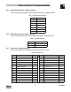
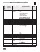
Parameter No.
1
smd
Register #
(hexadecimal
representation)
Parameter Name Range of Adjustment
2,
Modbus value (decimal value)
Factory
Default
PV400 PV507
C08 57 (39H) 57 (39H) Configuration
Relay Output
0 Ready
1 Fault
2 Motor is running
3 Motor is running - CW rotation
4 Motor is running - CCW rotation
5 Output frquency = 0Hz
6 Frequency setpoint reached
7 Threshold (C17) exceeded
8 Current limit reached
9 Feedback within min/max alarm range
10 Feedback outside min/max alarm range
1
C09 58 (3AH) 58 (3AH) Network Address 1 - 247 1
C10 59 (3BH) 59 (3BH) Minimum Output Freq. 0 - 2400 (0.0 - 240 Hz) 0.0 Hz
C11 60 (3CH) 60 (3CH) Minimum Output Freq. 75 - 2400 (7.5 - 240 Hz) 50.0 Hz
C12 61 (3DH) 61 (3DH) Acceleration Time 0 - 9990 (0.0 - 999 sec) 5.0 sec
C13 62 (3EH) 62 (3EH) Deceleration Time 0 - 9990 (0.0 - 999 sec) 5.0 sec
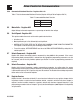
C14 63 (3FH) 63 (3FH) Operating Mode 0 Linear with Auto Boost
1 Square Law with Auto Boost
2 Linear with Constant V
min
Boost
3 Square Law with Constant V
min
Boost
2
C15 64 (40H) 64 (40H) V/f Reference Point 250 - 9990 (25.0 - 999 Hz) 50.0 Hz
C16 65 (41H) 65 (41H) V
min
Boost 0 - 400 (0.0 - 40.0%) 4.0%
C17 66 (42H) 66 (42H) Frequency Threshold 0 - 2400 (0.0 - 240 Hz) 0.0 Hz
C18 67 (43H) 67 (43H) Chopper Frequency 0 4kHz
1 6kHz
2 8kHz
3 10kHz
2
C21 68 (44H) 68 (44H) Slip Compensation 0 - 400 (0.0 - 40.0%) 0.0%
C22 69 (45H) 69 (45H) Current Limit 30 - 150% 150%
C24 70 (46H) 70 (46H) Accel Boost 0 - 200 (0.0 - 20.0%) 0.0%
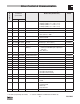
C31 71 (47H) Analog Input Deadband 0 Deadband Enabled
1 Deadband Disabled
0
C34 71 (47H) 72 (48H) Configuration
Analog Input
0 0...10V
1 0...5V
2 0...20mA
3 4...20mA
4 4...20mA Monitored
0
C36 72 (48H) 73 (49H) Voltage (DCB)
DC Injection Brake
0 - 500 (0.0 - 50.0%) 4.0%
C37 73 (49H) 74 (4AH) Fixed Setpoint 1 (JOG1) 0 - 9990 (0.0 - 999) 20.0 Hz
1 = The drive's programming code number; 2 = Selections in bold are for
smd
models with PV507 only.