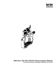
SMVector RS-485 LECOM Communication Module Communications Interface Reference Guide
About these instructions This documentation applies to the RS-485 / LECOM communications option for the SMVector inverter and should be used in conjunction with the SMVector Operating Instructions (Document SV01) that shipped with the drive. These documents should be read in their entirety as they contain important technical data and describe the installation and operation of the drive and this option.
Contents 1 Safety Information......................................................................................................................................................2 1.1 1.2 1.3 1.4 1.5 2 Introduction................................................................................................................................................................4 2.1 2.2 3 5.4 5.5 Configuration and Control Registers............................................................................
Safety Information 1 Safety Information 1.1 General Some parts of Lenze controllers (frequency inverters, servo inverters, DC controllers) can be live, moving and rotating. Some surfaces can be hot. Non-authorized removal of the required cover, inappropriate use, and incorrect installation or operation creates the risk of severe injury to personnel or damage to equipment.
Safety Information 1.5 Operation Systems including controllers must be equipped with additional monitoring and protection devices according to the corresponding standards (e.g. technical equipment, regulations for prevention of accidents, etc.). You are allowed to adapt the controller to your application as described in the documentation. DANGER! • After the controller has been disconnected from the supply voltage, do not touch the live components and power connection until the capacitors have discharged.
Introduction 2 Introduction This reference guide assumes that the reader has a working knowledge of the LECOM Protocol and familiarity with the programming and operation of motion control equipment. This guide is intended as a reference only. 2.1 Module Specifications Table 2 identifies the LECOM serial communication specifications.
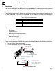
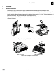
Installation 3 Installation 3.1 Mechanical Installation 1. Ensure that for safety reasons the AC supply has been disconnected before opening the terminal cover. 2. Insert the RS-485 option module in the terminal cover and securely “click” into position as illustrated in Figure 2. 3. Wire the network cables to the connector provided, as detailed in paragraphs 3.2 (RS-485 Terminal Block) and 3.3 (Electrical Installation), and plug the connector into the option module. 4.
Installation 3.2 RS-485 Terminal Block For a LECOM network, wire the RS-485 connector as detailed in Table 3. Table 3: RS-485 Pin Designation Terminal Description Important 1 Earth ground / shield For reliable communication make sure terminal is connected to the LECOM network GND/common. If only two wires are used (TXA and TXB) in the network, connect Terminal 1 to chassis/earth ground.
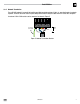
Installation 3.3.4 Network Termination For an RS-485 network it is essential to install the specified termination resistors (120W), i.e. one at both ends of a network segment. Failure to do so will result in signals being reflected back along the cable which will cause data corruption. An external 120W 1/4W resistor can be connected as shown in Figure 5.
Commissioning 4 Parameters for use with RS-485/LECOM 4.1 Drive Communication Parameters The parameters listed in Table 5 are always present on the drive, even if there is no communication module installed. Table 5: Drive Communication Parameters Code No.
Commissioning 4.2 RS485 LECOM-Specific Parameters The parameters listed in Table 6 are only present in the drive if there is an RS485 communication module installed, P400 = 7 and the module is online (P402 = 3). Table 6: RS485 LECOM-Specific Parameters Code No.
Commissioning 5 LECOM Protocol Details 5.1 LECOM - A/B Protocol Description The LECOM-A/B protocol is used to exchange data between SMV controllers and a host. The LECOM-A/B protocol is based on DIN 66019, ISO 1745 and ANSI X3.28 (category 2.5 and A2, A4). These standards are similar to each other and describe the control mode of a transmission section of a transmission system. The host (the master) can communicate with a slave (SMV controller) in three modes: • RECEIVE (refer to 6.
Commissioning 5.3 Code Number (C1, C2) 5.3.1 Standard Addressing The meaning of the code numbers and the assigned parameters can be obtained from the code table (in section 9) and the SMV Operating Instructions Manual (SV01, section10). When transmitting data, the code number is coded as follows: The following calculation determines the two ASCII digits from the code number (value range: 0 ... 6229) (value range: 48 dec ...
Commissioning 5.3.3 Addressing via Input Selection Simple LECOM-A/B drivers, which only use the standard addressing, cannot address subcodes. The input selection C0248 has been developed to offer the possibility of addressing the subcodes. When using the standard addressing, the value entered in C0248 is always considered as the subcode. The code C0248 can always be accessed via number 248, independent of the currently set code bank and the sub code used.
Commissioning The abbreviations have the following meanings: VK1 to VK6 Integers .
Commissioning Parameter values in the octet string format (VO) The LECOM-A/B protocol includes the octet string format (VO) with which it is possible to transfer data blocks. The character sequence corresponds to the filing in the memory (ascending order), i.e. the character transmitted first is the data block nibble with the lowest address.
Commissioning 6 LECOM Message Details 6.1 Telegram Response The SMV controller must return an acknowledgement to the host. The only exceptions to this are when a broadcast telegram is received or when the controller address is not correct. These telegrams do not require an acknowledgement. The SMV controller sends two types of acknowledgements: • Negative acknowledgement (NAK = 15hex), if: −− a fault (e.g.
Commissioning Example 1 The current speed setpoint (code number C46) is to be read with the bus address 01 at the controller. The host sends the following RECEIVE telegram EOT 0 1 4 6 ENQ The controller can respond in three different ways: STX 4 6 3 5 . 4 ETX BCC Valid request: The current value of the parameter C46 is 35.
Commissioning 6.4 Broadcast / Multicast In a bus network, the command BROADCAST is to address all devices or a group of devices (multicast) at the same time. The structure of the BROADCAST telegram is similar to the structure of the SEND telegram. The only exception is that it does not return an acknowledgement. The devices can be selected via their controller addresses. The controller addresses listed in Table 8 are reserved for a BROADCAST telegram.
Commissioning 7 Commissioning 7.1 Drive Monitoring The network can always read drive parameters as long as the LECOM communications are enabled (i.e. P400 = 7) and configured properly (see P410-411). For monitor only operation, set P420 = 0. 7.2 Drive Programming and Control Network Control must be enabled for the network to program drive parameters or take control of a drive. This is done by: 1. Setting P121…P124 equal to 09 (NET ENABLE) and asserting the corresponding TB-13x terminal 2.
Commissioning 8 Drive Registers 8.1 Configuration and Control Registers Registers #1 through #1099 are reserved for registers that are only available over the network and cannot be accessed via the drive’s local keypad.
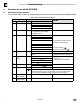
Commissioning Code Parameter Name Number C0135 Controller Control Word Default Range of Adjustment Bit Description 0-1 JOG1, JOG2, JOG3 0 = C0046 active 1 = JOG1 (C0037) active 2 = JOG2 (C0038) active 3 = JOG3 (C0039) active 2 Rotation command 0 = CW 1 = CCW 3 Quick Stop 0 = QSP not active 1 = QSP active 4-8 Reserved 9 Controller inhibit 0 = No controller inhibit 1 = Controller inhibit 10 Reserved 11 Trip fault reset 0 -> 1 Edge from 0 to 1 causes TRIP reset 12-13 Reserved 14 DC Brake (DC
Commissioning Code Parameter Name Number C0150 Controller Status Word Default Range of Adjustment Bit Description 0 Reserved 1 Power stage transistors energized 2 Current Limit reached 3 Reserved 4 Setpoint Frequency reached 5 Actual frequency above threshold C17 6 Actual frequency == 0Hz 7 Controller inhibit 0 = No controller inhibit 1 = Controller inhibit Important Read only 8 - 11 Controller status 0 = No error 1 = Error 12 Overtemperature fault 13 DC Bus overvoltage 14 Directio
Commissioning Code Parameter Name Number 8.1.1 Default Range of Adjustment Important C0200 Software Identification Software identification string: example “33SSSMD-M_14000” LECOM Format = VS Read only C0201 Software Generation Date Software generation date: example “2008-10-18” LECOM Format = VS Read only C1050 Network Controlled Digital Output (TB14) + Relay 0 = de-energized 1 = energized bit 9: TB-14 state bit 10: Relay state other bits are not used Refer to section 8.1.
Commissioning 9 Programming Parameters There is an offset of 1000 between the Drive Programming Parameter numbers and the code numbers used in the LECOM messages. For example, if you want to read Drive Programming Parameter P103 (Maximum Frequency) over the LECOM network, you would read code number 1103. 9.1 Fault History (P500) Value 0 1 2 3 4 5 6 7 8 9 10 11 12 13 14 15 16 17 18 19 20 21 22 23 24 25 26 27 28 29 30 31 32 33 34 35 36 Display F.OF F.OF1 F.AF F.rF F.HF F.LF F.PF F.GF F.IL F.dbF F.SF F.
Commissioning 9.2 Drive ID (P502) This register returns an index value that is associated with the voltage and power rating of the drive. Table 10 lists the drive configuration by Index number. Table 10: Drive ID Index Input Voltage Power Rating 8 240 VAC, Single-Phase 0.33 HP (0.25 kW) 12 13 14 240 VAC Single or Three-Phase 2 HP (1.5 kW) 3 HP (2.2 kW) 21 0.5 HP (0.37 kW) 23 1 HP (0.75 kW) 24 1.5 HP (1.1 kW) 25 2 HP (1.5 kW) 26 28 240 VAC Three-Phase 3 HP (2.2 kW) 5 HP (4 kW) 29 7.
Commissioning 9.
Troubleshooting and Fault Elimination 10 Troubleshooting and Fault Elimination 10.1 Faults Table 11 lists the faults common to the LECOM communications module. Table 11: Faults Fault Code Fault F 10.2 Cause Remedy f Module to Drive communication time out Connection between drive and Check cable and connection module is not made. between module and drive 1 Network Time-out Fault Drive under NETWORK control and network communications have been lost.
Lenze AC Tech Corporation 630 Douglas Street • Uxbridge, MA 01569 • USA Sales: (508) 278-9100 • Service (508) 217-9100 www.lenzeamericas.