SMVector Additional I/O Module Installation and Operation Manual
About These Instructions This documentation applies to the optional Additional I/O module for the SMVector inverter and should be used in conjunction with the SMVector Operating Instructions (Document SV01) that shipped with the drive. These documents should be read in their entirety as they contain important technical data and describe the installation and operation of the drive. NOTE To use the I/O Module with SMVector drives rated at 0.33 to 10 HP (0.25 to 7.
Contents 1 Safety Information..............................................................................................................1 1.1 2 3 4 Warnings, Cautions and Notes...............................................................................1 1.1.1 General.....................................................................................................1 1.1.2 Application................................................................................................1 1.1.
Safety Information 1 Safety Information 1.1 Warnings, Cautions and Notes 1.1.1 General Some parts of Lenze controllers (frequency inverters, servo inverters, DC controllers) can be live, moving and rotating. Some surfaces can be hot. Non-authorized removal of the required cover, inappropriate use, and incorrect installation or operation creates the risk of severe injury to personnel or damage to equipment.
Safety Information 1.1.4 Electrical Connection When working on live drive controllers, applicable national regulations for the prevention of accidents (e.g. VBG 4) must be observed. The electrical installation must be carried out in accordance with the appropriate regulations (e.g. cable cross-sections, fuses, PE connection). Additional information can be obtained from the regulatory documentation.
Introduction 2 Introduction This manual provides installation and operational data specific to the Additional I/O Module for the SMVector series inverters. This manual is a supplement (not a substitution for) the standard SMVector - Frequency Inverter Operating Instructions (document number SV01). This document assumes that the reader has a working knowledge of the standard SMVector Frequency Inverter and has familiarity with the programming and operation of the SMVector Frequency Inverter.
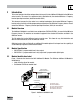
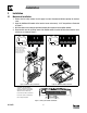
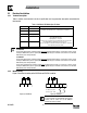
Installation 3 Installation 3.1 Mechanical Installation 1. Ensure that for safety reasons the AC supply has been disconnected before opening the terminal cover. 2. Insert the Additional I/O module in the terminal cover and securely “click” into position as illustrated in Figure 2. 3. Wire the cables to the connector provided and plug the connector into the option module. 4.
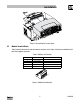
Installation Figure 3: Re-Installing the Terminal Cover 3.2 Module Terminal Block Table 2 identifies the terminals and describes the function of each. Figure 4 illustrates the Additional I/O 5 pole 5mm pluggable connector. Table 2: Additional I/O Terminals Terminal Function 19 Relay N.O. Description 20 Relay Common 21 Relay N.C.
Installation 3.3 Electrical Installation 3.3.1 Terminal Description Table 3 contains each terminal's electrical specification and any parameter description associated with that terminal. Table 3: Additional I/O Module Specifications Terminal Function Description 19 Relay N.O. 20 Relay Common Relay output configurable with P441, P144 AC 250 V / 3 A 17 DC 24 V / 2 A … 240 V / 0.22 A, non-inductive 21 Relay N.C.
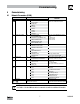
Commissioning 4 Commissioning 4.1 Network Parameters (P400) Code No. Name Possible Settings Default Selection p400 Network Protocol IMPORTANT 0 Not Active This parameter setting is based upon the network or I/O module that is installed. 1 Remote Keypad 2 Modbus RTU 3 CANopen 4 DeviceNet 5 Ethernet 6 Profibus 7 Lecom-B 8 I/O Module p401 Module Type Installed 0 0 No Module Installed 1 Basic I/O (0x0100, 1.0.0) 2 RS485/Rem. Keypad (0x0200, 2.0.0) 3 CANopen (0x0300, 3.0.
Commissioning 4.2 Additional I/O Module Parameters In addition to the parameters detailed in the SMVector Frequency Inverter Operating Instructions (SV01), installing the Additional I/O Module provides access to supplementary parameters exclusive to the Additional I/O Module. Table 4 lists these supplementary parameters. Table 4: Additional I/O Module Parameters Code No.
Commissioning Code No. Name p441 Relay Output TB-19, 20, 21 P144 Digital Output Inversion Possible Settings Default Selection 0 0 None IMPORTANT Disables the output 1 Run Energizes when the drive is running 2 Reverse Energizes when reverse rotation is active 3 Fault De-energizes when the drive trips, or power is removed 4 Inverse Fault Energizes when the drive trips 5 Fault Lockout P110 = 3...
Commissioning 4.3 Display Parameter P530 allows monitoring of the control terminal points and common drive conditions. An illuminated LED segment indicates: • the protective circuit is active (LED 1) • the Logic Assertion Switch is set to High (+) • input terminal is asserted (LED 2) • output terminal is energized (LED 4) • the Charge Relay is not a terminal, this segment will be illuminated when the Charge Relay is energized (LED 4).
Lenze AC Tech Corporation 630 Douglas Street • Uxbridge MA 01569 • USA Sales: 800-217-9100 •Service: 508-278-9100 www.lenzeamericas.