
Install Instructions

Bulletin G-AT
August, 2018
1360 Elmwood Avenue, Cranston, RI 02910 USA
Phone: 401.461.1200 Fax: 401.941.5310
Email: info@leonardvalve.com
Web Site: http://www.leonardvalve.com
INSTALLATION ADJUSTMENT SERVICE
ALLTERNATIVE TEMPERATURE
THERMOSTATIC WATER MIXING VALVES
TYPE TM-50-AT, 80-AT, 150-AT, 200-AT,
TYPE TM-50-AT-LF, 80-AT-LF, 150-AT-LF, 200-AT-LF
IMPORTANT! Provide valve serial number, (stamped on cover of valve) when ordering parts!!
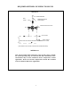
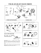
OUTLET
HOT INLET
COLD INLET
C
H
LEONARD
THERMOSTATIC
INSTALLATION
1. Valve should be installed at a location where it can
easily be cleaned, adjusted or repaired.
2. The inlets are clearly marked on the valve body casting.
Connect the hot water into the inlet marked "H" and cold
water into the inlet marked "C". These are NOT to be
confused with the "C-H" markings on the front cover.
3. Union angle strainer checkstops furnished must be
installed on both supply lines as shown above.
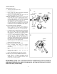
4. A shutoff valve must be installed on the outlet pipe.
Type TM valves do not have a built-in shutoff.
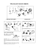
5. Use solder, or thread sealant sparingly. Supply pipes
should be flushed before the valve is connected. Flush
outlet pipe and valve as soon as it is connected.
Maximum Operating Pressure 125PSI (860 KPA) for
Hot and Cold Water.
NOTE: Valve is not to be used for domestic hot water distribution. Please see
Leonard Valves complete line of ASSE 1017 certified mixing valves for
Domestic hot water.
REMEMBER! THIS IS A CONTROL SYSTEM WHICH MUST BE CLEANED AND
MAINTAINED ON A REGULAR BASIS (SEE MAINTENANCE GUIDE AND RECORD
MGR-1000).
!
WARNING: This product can expose you to
chemicals including lead, which is known to the State
of California to cause cancer. For more information, go
to www.P65Warnings.Ca.gov