
User Manual

Page 1 of 2
Installation, Operating and
Maintenance Instructions
Supplement
10/2.5.1.B
Rev. 0
12501 Telecom Drive, Tampa Florida 33637
AEROFLOW SUPPLEMENT
Special “Upseating Mini-P” Actuator Adjustment
TABLE OF CONTENTS
INSTALLATION .........................................................................................................................................1
MAINTENANCE .........................................................................................................................................2
ILLUSTRATION INDEX
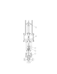
FIGURE 1 – VALVE ASSEMBLY SHOWN IN OPEN POSITION ......................................................................................................... 2
INSTALLATION
NOTE: Refer to Fig. 1 for installation.
1. Slide the seat-ring over the plug stem (1) and
lower the assembly down into the valve body with
the seat ring gasket (follow valve IOM for
assembly of valve). Note: Do not allow the valve
plug to slam into the bottom of the valve. Lower
the valve stem slowly until it comes to rest.
2. Disassemble the stem coupling (3) cap screws.
3. Mount the actuator to the top of the valve.
4. With the actuator mounted to the valve, the
actuator piston (5) will be in the “up” (retracted)
position (no air in actuator).
5. Thread the stem coupling (3) all the way down
onto the valve stem (1) . The packing in the
valve should be “loose” at this point to allow the
valve plug to retract into the valve body.
6. Ensure that the valve spring tensioner (4) is
completely unadjusted.
7. By placing air to the top of the actuator stroke the
actuator down 3.25” (air pressure not exceed 80
psi)
8. Pull up on the valve stem (1) and assemble the
stem coupling (3), by tightening the coupling cap
screws. The valve should now stroke about .75”.
(If this procedure is not followed, the valve
stem can be driven down into the valve lower
body and damage may occur to the valve
body, trim or both.)
9. The correct valve stroke for this trim set is 1”.
Put 80 psig air to the top of the actuator, unscrew
the valve stem (1) from the stem coupling (3) ¼ -
1 full turn at a time. After each adjustment stroke
the valve until 1” stroke is obtained.
10. Tighten the valve locking nut (2). The spring
tensioning nut (4) should not need to be
CAUTION!
All warnings from valve IOM must be followed.
CAUTION!
Keep all extremities away from moving parts on the
actuator. Failure to do so may cause injury or even
death.