
User guide

- 9 -
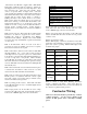
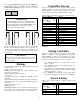
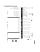
Terminal Board Layout
I
N
P
U
T
S
B
A
C
O
U
T
P
U
T
S
O
U
T
P
U
T
S
P
O
W
E
R
Conductivity probeI-1
BAC pressure reading (Output)I-2
Pressure sensorI-3
High water floatI-4
Stop water feedI-5
Start water feedI-6
Low level cut-offI-7
Optional inputI-8
UnusedI-9
B-1
B-2
B-3
B-4
B-5
B-6
B-7
B-8
B-9
B-10
Dry contact to BAC for "power on"
Dry contact to BAC for "blow down occuring"
Dry contact to BAC for "low water"
Dry contact to BAC for "water feed"
Dry contact to BAC for "high water"
Dry contact to BAC for "high pressure"
Dry contact to BAC for "low pressure"
Dry contact to BAC for "spare"
Dry contact to BAC for "alarm"
Dry contact to BAC for "optional
0-1
0-2
0-3
0-4
0-5
24V AC output to "feed water"
24V AC output to "high water cut-off"
24V AC output to "steam control valve"
24V AC output to "blow down valve"
24V AC output to "optional"
= Wire numbers
12
11
4
7
8
9
10
3
18
17
P1 P2
24V AC PWR
from transformer
24V AC 1 Amp
for
Remote Control
NC
NO
Com
NC
NO
Com
NC
NO
Com
NC
NO
Com
NC
NO
Com
NC
NO
Com
NC
NO
Com
NC
NO
Com
NC
NO
Com
NC
NO
Com
To conductivity probe (yellow) (type 1 only)
Ground (green)
0-10V DC to BAC for pressure reading
Ground
+ output (white)
Common (black)
+ input (red)
14
13
High water float (brown)
Common
Stop water feed float (blue)
Common
Start water float (yellow) or 1 from #157 NC
Common or 2 from #157 NC
Low level cut-off float (red) or 5 from #157 NO
Float common (black) or 6 from #157 NO
Optional input NO
Optional input NO
Unused
16
15
2
1
6
5