LevelOne DSA-1000 / PRT-1000 Device Server / Thermal Printer User Manual V1.
TABLE OF CONTENTS 1. INTRODUCTION ...................................................................................................................................................................... - 3 2. DEVICE OVERVIEW ............................................................................................................................................................... - 7 3. HARDWARE SETUP ..........................................................................................................
1. Introduction Overview of Network Ticket Generator Whether you are “operating a wireless hotspot service for generating revenue” or “providing free but controlled wireless internet access to guests”, it would be handy to both the operators and the wireless users if the account information (such as username, password, SSID and etc.) can be readily output to Thermal Printers and printed out as account tickets. DSA-1000 is designed specifically to operate in conjunction with specific Controllers/Gateways.
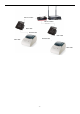
Below are two network diagrams examples using Network Ticket Generator combo set.
Ethernet Cable WHG-1000 Ethernet Cable DSA-1000 RS232 Cable DSA-1000 RS232 Cable PRT-1000 PRT-1000 -5-
Application Diagram DSA-1000 DSA-1000 PRT-1000 PRT-1000 Though DSA-1000 is specifically designed to for on-demand account generation and operate Thermal Printers, it can also be deployed independently to connect other RS232 devices to an Ethernet network for remote operation. If you will be deploying DSA-1000 independently to manage other serial devices, please carefully set the Serial Settings in DSA-1000 to match the operating needs of your serial device.
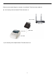
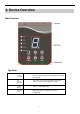
2. Device Overview Panel Overview Top Panel Adapter Socket (12V/1A) The power socket for connecting to an external power source through the power adapter provided in the package. DC Socket (DC12V) The power socket for connecting to an external power source through a DC power supply. Restart Button Press to restart DSA-1000. Ethernet Port Ethernet port for connecting to a Controller/Gateway.
Bottom Panel COM 1 Serial Port for connection with a Thermal Printer. COM 2 Serial Port for connection with a Thermal Printer. Used for back up when COM 1 malfunctions. Main Panel LED indicators Power Turned on when properly connect to power supply. COM 1 Turned on when output is switched to COM1. Note: COM 2 When COM 1 and COM 2 are blinking simultaneously, this means that Terminal Server configuration is not set correctly.
For switching the output to COM1 or COM2. Press this button followed by selecting a number and press Enter will perform a specific action. The available combinations are as follows: FUNTION + 1 + ENTER: Print out the IP address of DSA-1000. FUNTION + 8 + ENTER: Enter panel test mode. FUNTION + 9 + ENTER: Reset DSA-1000 to factory default. FUNTION + 0 + ENTER: Lock the panel of DSA1000. To Unlock select your lock number and press ENTER Decrease the numeric display for selecting a billing plan number.
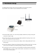
3. Hardware Setup The following diagram illustrates how to connect DSA-1000 to the Thermal Printer and Gateways/Controllers. Please follow the steps described below to install hardware: Ethernet Cable WHG-1000 DSA-1000 RS232 Cable PRT-1000 1. Attach DSA-1000 to a power source, either through adaptors provided in the package or through DC socket with a DC power supply. 2.
Note: If you are unable to get a reply from pinging DSA-1000, please refer to System Configuration and check that the network settings of DSA-1000 and Gateway/Controller interface connected to are under the same subnet.
4. System Configuration DSA-1000 is designed specifically to operate in conjunction with all Gateways/Controllers. If you are not using default settings, before connecting DSA-1000 to your Gateway/Controller, some configurations steps are required. The configuration instructions for Gateways/Controllers and DSA-1000 are covered in the following sections. 4.1 DSA-1000 DSA-1000 supports web based configuration. By factory default, DSA-1000 web interface can be accessed with IP address: 192.168.1.
Step2: Attach DSA-1000 to a power supply using the adapter provided in the package. Connect the administrator PC to the Ethernet Port of DSA-1000 via an Ethernet cable. Launch a web browser and type in the default IP address of DSA-1000 in the address field (http://192.168.1.10), the web interface of DSA-1000 should appear.
4.2 Gateway/Controller Configuration procedures are similar on all Gateway/Controller models, the following instruction steps uses WHG-1000 as illustration. Note: the screenshots may be slightly different for your Gateway/Controller model. Step1: Connect administrator PC to your Gateway/Controller and access the WMI (web management interface).
Step2: Enter the configuration page of the Service Zone which DSA-1000 will be connected to. Check to make sure that the network settings of DSA-1000 are under the same subnet as this service zone. Step3: Go to the configuration page for On-demand authentication; click Configure to edit Terminal Server settings. Enter the IP address (192.168.1.10) and Port (5000) of DSA-1000.
Step4: Edit and enable desired billing plans.
5. Operation Instructions After completing the Hardware Setup and the devices are physically connected, the system is ready for operation. This section will describe how to operate DSA-1000 to printout tickets for enabled billing plans. 1. Select an enabled billing plan number on DSA-1000 by or button. The numeric LED dis- play on the center of the device represents the billing plan number currently selected.
Appendix A. DSA-1000 Web Interface Summary The attribute setting in this web interface is for COM 1 only. COM 2 uses default settings that are unchangeable. Serial Settings (corresponding to Thermal Printer) Data Baud Rate Select the desired baud rate. (The number of characters per second transferred) Data Bits Select the number of bits in each character. Data Parity Choose between Even or Odd for error detection, or select None for no error detection.
Appendix E - Command Line Interface Network Settings Static IP Address The static IP address assigned to DSA1000. Static Subnet Mask The subnet mask of DSA-1000. Static Default Gateway The default gateway of DSA-1000. Static DNS Server Set the DNS server used by DSA-1000. Transmit Timer TCP transmit timer, set the desired value or use default value. When the timer expires for a sent packet, sender will retransmit the packet.
Appendix E - Command Line Interface Appendix B. Firmware Upgrade Software tools tftpd32 is required in the upgrade procedure, please download and install tftpd32 before you proceed further. Note: Tftpd32 can be downloaded from the following link: http://tftpd32.jounin.net/tftpd32.html Step1: Place the new firmware of DSA-1000 on a local location (for example desktop) in the PC that is accessing DSA-1000’s web interface and performing the upgrade.
Appendix E - Command Line Interface Step4: Click Apply of Firmware Upgrade in DSA-1000’s web interface. DSA-1000 will automatically restart and connect to tftpd32 server set in Step3 as a DHCP client, download the firmware and perform the upgrade. Progress can be observed on tftpd32. Step5: When complete, check the information displayed at Software Version, DSA-1000 have successfully upgraded to the new firmware.