LevelOne GSW-1641 16-Port Gigabit with 1-Port SFP Web Smart Switch User Manual Version 1.
FCC Certifications This Equipment has been tested and found to comply with the limits for a Class A digital device, pursuant to part 15 of the FCC Rules. These limits are designed to provide reasonable protection against harmful interference when the equipment is operated in a commercial environment. This equipment generates, uses, and can radiate radio frequency energy and, if not installed and used in accordance with the instruction manual, may cause harmful interference to radio communications.
Table of Contents UNPACKING INFORMATION ....................... 5 INTRODUCTION ............................................... 5 GENERAL DESCRIPTION ............................................................................ 5 KEY FEATURES ......................................................................................... 5 THE FRONT PANEL .................................................................................... 6 THE REAR PANEL .............................................................
VLAN..................................................................................................... 15 PVID ...................................................................................................... 16 AGGREGATION/ TRUNK CONFIGURATION ............................................... 17 QUALITY OF SERVICE .............................................................................. 18 MIRROR...................................................................................................
Unpacking Information Thank you for purchasing GSW-1641 Gigabit Web Smart Switch. Before you start, please verify that your package contains the following items: 1. 2. 3. 4. 5. One GSW-1641 Web Smart Switch One AC power cord Rack-mount brackets Stackable kit Manual CD Introduction General Description Easily boosting your networking throughput, LevelOne GSW-1641 provides you 16 10/100/1000Mbps gigabit ports that lead you to a real gigabit connection.
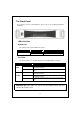
The Front Panel The front panel consists of LED indicators. Please refer to the following paragraph for information. LEDs Definition System LED The switch provides a power LED for the device. LED Power Status Steady Green Off Operation The switch is powered on The switch is powered off Port LEDs The switch provides one “1000M” LED and one “10/100M” LED for each port.
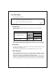
The Rear Panel The rear panel of the switch: Port Operation The auto-negotiation feature allows those ports running at one of the following operation modes: Media Speed 1000Mbps Duplex Mode Full Duplex Half Duplex Full Duplex Half Duplex Full Duplex 1000Mbps Full Duplex 10Mbps 10/100/1000Mbps(copper) 1000Mbps(Fiber) (mini GBIC required) 100Mbps Note: For the last port, when both the fiber and cooper interfaces are connected, the system adapts the fiber interface and disables the relevant cooper po
Installation This switch can be placed on your desktop directly, or mounted in a rack. Please refer to the instructions for installation. Before installing the switch, we recommend: 1. 2. 3. The switch is placed with appropriate ventilation environment. A minimum 25mm space around the unit is recommended. The switch and the relevant components are away from sources of electrical noise such as radios, transmitters and broadband amplifiers. The switch is away from environments beyond recommend moisture.
Installing Network Cables 1. Crossover or straight-through cable: All the ports on the switch support auto-MDI/MDI-X functionality. Both straight-through or crossover cables can be used as the media to connect the switch with PCs as well as other devices like switches, hubs or router. 2. Category 3,4,5 or 5eUTP/STP cable: To make a valid connection and obtain the optimal performance. An appropriate cable that corresponds to different transmitting/receiving speed is required.
Functional Description Jumbo Frame With Jumbo Frame supported, it is allowed for the switch to transport identical data in fewer frames. Hence helps to ensure fewer overheads, shorten processing time, and reduce interrupts. Note: To enable Jumbo Frame, Flow Control should be enabled in advance. Flow Control and Back Pressure Flow control and Back Pressure both contributes for lower and higher speed devices to communicate to each other hence ensures the correctness of data transmitting. The 802.
Management guide Access the Switch This section instructs you how to enter and proceed the advanced management capability, which can be accessed by internet browser over the network. To access the web-based management interface, you should configure the management station with an IP address and subnet mask that compatible to your switch. The factory default value of the switch: IP: 192.168.1.1 Subnet Mask: 255.255.255.0 Default Gateway: 192.168.1.254 1.
Homepage After authentication procedure, the “SYSTEM Configuration” page shows up as the Homepage. You may click the hyperlinks on the left side of each page to get access to each management function.
System The “System” window provides the switch information and allows users to configure the switch properties. Items MAC Address S/W Version IP Address Subnet Mask Gateway Management VLAN User Name Password System Name Functions The MAC address of this device.. The software version of this device. Setup the IP address of the switch Setup the Subnet Mask of the switch Setup the Gateway of the switch The VLAN group that is allowed to access the WEB-based management interface. The Login name.
Port This “Port Configuration” page shows the link status of each port and allows users to configure speed, flow control and Max frame size for each port. Items Link Mode Flow Control Max Frame length Functions Shows the link status of each port. The column lights green with the link speed while there is valid connection on this port. Select a speed for this port. “Auto Speed” enables auto-negotiation. “Disable” stop the port from functioning.
VLAN VLAN divides the network members into groups to reduce packets collisions and improve the network efficiency. The switch supports 802.1Q tag-based VLAN. Please follow the instructions to configure. To add new VLAN groups, 1. Fill in a VLAN id from 2 to 4094 in the “VLAN\Port” column. 2. Select the ports for each VLAN groups. 3. Click the “Apply” button to execute. To delete a VLAN group 1. Clear the members of this VLAN group by clicking those marked checkboxes. 2.
PVID When the VLAN-enabled switch receives a tagged packet, the packet will be sent to the port’s default VLAN according to the PVID (port VLAN ID) of the receiving port. Items Functions Port Port Number 1~16 Egress Select “tagged” in the drop list to enable the PVID checking and tag inserting of one port, and select “untagged” to cancel. For example, if an Egress-tagged port receives an untagged frame, it will be transmitted as a PVID tagged frame.
Aggregation/ Trunk Configuration To set up the port trunk groups, put the ports number into the same aggregation group. There are eight groups to choose. Don’t forget to click the “Apply” to save the setting. There are three aggregation modes for you to setup, SMAC (Source MAC), DMAC (Destination MAC), and XOR. SMAC mode selects the path of packets according to source MAC while DMAC mode selects path according to destination MAC.
Quality of Service QoS enhances the communication quality by giving different precedence to classified packets.
Port-based mode QoS: The port-based QoS allows users to configure certain ports as high or low priority. To give priority level for each port: 1. 2. 3. 4. Select “Port” in the “Mode” column for those ports that are going to perform port-based QoS. Click the “Apply” button. Click the “Port priority” button. The “Port Priority Setting” page shows up. Click on the drop list to specify priority levels. Click “Apply” to execute.
Tag based QoS: The tag-based QoS decides packet priority according to the tags that adding on the packets. To configure Tag-based QoS configuration: 1. 2. 3. 4. 5. Select “Tagged” in the “Mode” column for those ports that are going to perform tag-based QoS. Click the “Apply” button. Click the “Tag priority” button. The “Tag Priority Setting” page shows up. Select the port that you are going to configure from the drop list. Give the priorities as high or low for each Priority Tag types.
DSCP mode QoS: The DSCP mode QoS gives packet priority by the precedent types attaching on the incoming packets. The types of precedence: 000 - Routine 001 - Priority 010 - Immediate 011 - Flash 100 - Flash Override 101 - CRITIC/ECP 110 - Internetwork Control 111 - Network Control To configure DSCP Based QoS configuration: 1. 2. 3. 4. Select “DSCP” in the “Mode” column for those ports that are going to perform DSCP-based QoS. Click the “Apply” button. Click the “DSCP priority” button.
Mirror The “Mirror” function copies all the packets that are received or transmitted by the source port to the destination port. It allows administrators to analyze and monitor the traffic of the monitored ports. Mirror Configuration: 1. 2. 3. Select those ports that are going to be monitored by marking the checkboxes in “Monitor Port” column. Click the drop list in “Sniffer Port” column. Select a port as the administration port for monitoring those source ports. Click “Apply” to activate.
Rate Limit This “Rate Limit” page allows users to configure the rules for storm control. You may also limit the speed of incoming and outgoing frames for each port. To perform storm control: 1. 2. Click on each drop list to specify a speed for each frame type. Click the “Apply” button to execute your configuration. To restrict the incoming and outgoing speed for each port: 1. 2. Click the “Ingress” drop list to specify the speed of incoming frames for each port.
SNMP This device supports SNMP-management, which allows network administrators to monitor and configure this device with SNMP software. To allow this device to be managed via SNMP: 1. Select “enable” in the drop list. 2. Specify a trap IP. A trap IP is the destination port for sending trap information, which is usually the IP address of network administrators. 3. Fill in a name in the “Community Get” text box, which is the password for accessing MIB with read-only authority. 4.
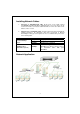
Discovery After installing series of LevelOne gigabit web smart switches(GSW-0841/1641/2440), the discovery management tool helps users to search and get access to those switches within the LAN. Note. The discovery tool lists the Maximum 16 devices respectively for auto and manual modes. Auto Search 1. Click the “Apply” button to start. 2. The devices being found are listed below. 3. Click the IP address hyperlink to get access to the device. Manual Add Add 1. Enter the IP address & name in the text box.
Statistics Overview The “Statistics Overview” is provided for users to see the general transmitting and receiving status of each port. You may click the “Clear” button to clean all statistics or click the “Refresh” button to renew the statistics. Detailed Statistics The “Detailed Statistics” is provided for users to see the detailed transmitting and receiving status of each port. Please click the hyperlinks above to select a port.
Warm Restart Restart: To restart the system, click the “Yes” button. The system will restart and show the authentication window. Please fill in the username and password to continue. Factory Default Restore Factory Default: To restore the factory default value, click the “Yes” button. Note: The IP address of the device will also be configured as factory-default setting, which is 192.168.1.1. Smart Boot This “Smart Boot” page allows users to select the booting flash of the device.
Software Upload This “Software Upload” page allows users to upgrade firmware for this switch. To perform firmware upgrade: 1. Click the “Browse” button. 2. Locate the firmware file. 3. Click the “Upload” button to execute. Note: This new firmware is going to be applied on the other flash that you select in “Smart Boot”, that is, the new firmware is going to be applied on the flash that is NOT chosen as the booting flash.
Product Specifications Standard IEEE802.3 10BASE-T IEEE802.3u 100BASE-TX IEEE802.3x full-duplex operation and flow control IEEE802.3ab/z 1000BASE-T IEEE802.1Q VLAN interoperability IEEE802.