GTL-5280 L2 Plus Managed Switch – 48 GE with 4 Combo SFP + 4 10GE SFP Plus User Manual I Ver. 1.
The information in this document is subject to change without notice. Unless the explicit written permission of Digital Data Communications Corporation, this document in whole or in part shall not be replicated or modified or amended or transmitted, in any from, or by any means manual, electric, electronic, electromagnetic, mechanical, optical or otherwise for any purpose.
operation, design, performance or implementation of the Software and related documentation that is confidential to LevelOne to any third party. Software and related documentation may be delivered to you subject to export authorization required by governments of Taiwan and other countries. You agree that you will not export or re-export any Software or related documentation without the proper export licenses required by the governments of affected countries. LIMITED SOFTWARE WARRANTY.
Table of Contents INTRODUCTION ......................................................................................................................................... 1 CHAPTER 1 OPERATION OF WEB-BASED MANAGEMENT ................................................. 2 CONNECTING NETWORK DEVICES ................................................................................................ 5 TWISTED-PAIR DEVICES ................................................................................................
3-4.3 MSTI Priorities ........................................................................................................................... 66 3-4.4 CIST Ports .................................................................................................................................. 67 3-4.5 MSTI Ports .................................................................................................................................. 69 3-4.6 Bridge Status .........................................
3-14.9 DSCP Classification ............................................................................................................... 163 3-14.10 QoS Control List Configuration ............................................................................................ 164 3-14.11 QCL Status ............................................................................................................................ 167 3-14.12 Storm Control ...............................................................
5-5 DIAGNOSTICS .................................................................................................................................... 241 5-5.1 Ping ........................................................................................................................................... 241 5-5.2 Ping6 ......................................................................................................................................... 242 5-5.3 VeriPHY ....................................
INTRODUCTION Overview In this user’s manual, it will not only tell you how to install and connect your network system but configure and monitor the GTL-5280 by (RS-232) serial interface or through the web and Ethernet ports step-by-step. Many explanations in detail of hardware and software functions are shown as well as the examples of the operation for web-based interface.
Chapter 1 Initial Configuration Operation of Web-based Management This chapter instructs you how to configure and manage the GTL-5280 through the web user interface. With this facility, you can easily access and monitor through any one port of the switch all the status of the switch, including MIBs status, each port activity, Spanning tree status, port aggregation status, multicast traffic, VLAN and priority status, even illegal access record and so on.
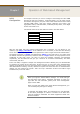
NOTE: AS GTL-5280 the function enable dhcp, so If you do not have DHCP server to provide ip addresses to the switch, the Switch default ip 192.168.1.1 Figure 1 The login page NOTE: If you need to configuration the function or parameter then you can refer the detail in the User Guide. Or you could access to the Switch and click the "help" under the web GUI and the switch will pop-up the simple help content to teach you how to set the parameters.
GTL-5280 web help function: 4
CONNECTING NETWORK DEVICES TWISTED-PAIR DEVICES CABLING GUIDELINES The switch is designed to be connected to 10, 100 or 1000Mbps network cards in PCs and servers, as well as to other switches and hubs. It may also be connected to remote devices using optional SFP transceivers. Each device requires an unshielded twisted-pair (UTP) cable with RJ-45 connectors at both ends. Use Category 5, 5e or 6 cable for 1000BASE-T connections, Category 5 or better for 100BASE-TX connections.
Step2. If the device is a network card and the switch is in the wiring closet, attach the other end of the cable segment to a modular wall outlet that is connected to the wiring closet. (See the section “Network Wiring Connections.”) Otherwise, attach the other end to an available port on the switch. Make sure each twisted pair cable does not exceed 100 meters (328 ft) in length. NOTE: Avoid using flow control on a port connected to a hub unless it is actually required to solve a problem.
System Configuration Chapter 2 This chapter describes the entire basic configuration tasks which includes the System Information and any manage of the Switch (e.g. Time, Account, IP, Syslog and SNMP.) 2-1 System Information After you login, the switch shows you the system information.
The model name of this device. System description: As it is, this tells what this device is. Here, it is “44-Port 10/100/1000BaseT + 4 (100/1G) SFP Combo + 4 (1G/10G) SFP+ PoE+ L2 Plus Managed Switch”. Location: Basically, it is the location where this switch is put. User-defined. Contact: For easily managing and maintaining device, you may write down the contact person and phone here for getting help soon. You can configure this parameter through the device’s user interface or SNMP.
2-1.2 Configuration You can identify the system by configuring the contact information, name, and location of the switch. Web interface To configure System Information in the web interface: 1. Click System, System Information, Configuration. 2. Write System Contact, System Name, System Location information in this page. 3. Click Apply Figure 2-1.
2-1.3 CPU Load This page displays the CPU load, using an SVG graph. The load is measured as averaged over the last 100ms, 1sec and 10 seconds intervals. The last 120 samples are graphed, and the last numbers are displayed as text as well.In order to display the SVG graph, your browser must support the SVG format. Consult the SVG Wiki for more information on browser support. Specifically, at the time of writing, Microsoft Internet Explorer will need to have a plugin installed to support SVG.
2-2 Time This page configure the switch Time. Time configure is including Time Configuration and NTP Configuration 2-2.1 Manual The switch provides manual and automatic ways to set the system time via NTP. Manual setting is simple and you just input “Year”, “Month”, “Day”, “Hour”, “Minute” and “Second” within the valid value range indicated in each item. Web Interface To configure Time in the web interface: 1. Click Time , Manual. 2. Specify the Time parameter in manual parameters. 3. Click Apply.
The switch supports valid configurable day light saving time is –5 ~ +5 step one hour. The zero for this parameter means it need not have to adjust current time, equivalent to in-act daylight saving. You don’t have to set the starting/ending date as well. If you set daylight saving to be non-zero, you have to set the starting/ending date as well; otherwise, the daylight saving function will not be activated. Time Set Offset: Provide the Daylight saving time set offset.
2-2.2 NTP NTP is Network Time Protocol and is used to sync the network time based Greenwich Mean Time (GMT). If use the NTP mode and select a built-in NTP time server or manually specify an user-defined NTP server as well as Time Zone, the switch will sync the time in a short after pressing button. Though it synchronizes the time automatically, NTP does not update the time periodically without user’s processing. Time Zone is an offset time off GMT.
2-3 Account In this function, only administrator can create, modify or delete the username and password. Administrator can modify other guest identities’ password without confirming the password but it is necessary to modify the administrator-equivalent identity. Guest-equivalent identity can modify his password only. Please note that you must confirm administrator/guest identity in the field of Authorization in advance before configuring the username and password.
Privilege Level : The privilege level of the user. The allowed range is 1 to 15. If the privilege level value is 15, it can access all groups, i.e. that is granted the fully control of the device. But others value need to refer to each group privilege level. User's privilege should be same or greater than the group privilege level to have the access of that group. By default setting, most groups privilege level 5 has the read-only access and privilege level 10 has the read-write access.
2-3.2 Privitege Level This page provides an overview of the privilege levels. The switch provides user set Account, Aggregation,Diagnostics,EEE,GARP,GVRP,IP, IPMC Snooping LACP LLDP LLDP MED MAC Table MRP MVR MVRP Maintenance Mirroring POE Ports Private VLANs QoS SMTP SNMP Security Spanning Tree System Trap Event VCL VLANs Voice VLAN Privilege Levels form 1 to 15 . Web Interface To configure Privilege Level in the web interface: 1. Click SYSTEM, Account, Privilege Level. 2. Specify the Privilege parameter.
Parameter description: Group Name The name identifying the privilege group. In most cases, a privilege level group consists of a single module (e.g. LACP, RSTP or QoS), but a few of them contains more than one. The following description defines these privilege level groups in details: System: Contact, Name, Location, Timezone, Log. Security: Authentication, System Access Management, Port (contains Dot1x port, MAC based and the MAC Address Limit), ACL, HTTPS, SSH, ARP Inspection and IP source guard.
2-4 IP IP is an acronym for Internet Protocol. It is a protocol used for communicating data across an internet network. IP is a "best effort" system, which means that no packet of information sent over is assured to reach its destination in the same condition it was sent. Each device connected to a Local Area Network (LAN) or Wide Area Network (WAN) is given an Internet Protocol address, and this IP address is used to identify the device uniquely among all other devices connected to the extended network.
Parameter description: DHCP Client : Enable the DHCP client by checking this box. If DHCP fails and the configured IP address is zero, DHCP will retry. If DHCP fails and the configured IP address is non-zero, DHCP will stop and the configured IP settings will be used. The DHCP client will announce the configured System Name as hostname to provide DNS lookup. IP Address : Provide the IP address of this switch in dotted decimal notation.
2-4.2 IPV6 This section describes how to configure the switch-managed IPv6 information. The Configured column is used to view or change the IPv6 configuration. And the Current column is used to show the active IPv6 configuration. Configure the switch-managed IPv6 information on this page. The Configured column is used to view or change the IPv6 configuration. The Current column is used to show the active IPv6 configuration. Web Interface To configure Management IPv6 of the switch in the web interface: 1.
2-5 Syslog The Syslog is a standard for logging program messages . It allows separation of the software that generates messages from the system that stores them and the software that reports and analyzes them. It can be used as well a generalized informational, analysis and debugging messages. It is supported by a wide variety of devices and receivers across multiple platforms. 2-5.
2-5.2 Log This section describes that display the system log information of the switch Web Interface To display the log configuration in the web interface: 1. Click Syslog, Log. 2. Display the log information. Figure2- 5.2: The System Log configuration Parameter description: Auto-refresh To evoke the auto-refresh icon then the device will refresh the log automatically. Level level of the system log entry. The following level types are supported: Information level of the system log.
2-5.3 Detailed Log This section describes that display the detailed log information of the switch Web Interface To display the detailed log configuration in the web interface: 1. Click Syslog, Detailed Log. 2. Display the log information. Figure2- 5.3: The Detailed System Log Information Parameter description: ID The ID (>= 1) of the system log entry. Message The detailed message of the system log entry. Upper right icon (Refresh, clear,….
2-6 SNMP Any Network Management System (NMS) running the Simple Network Management Protocol (SNMP) can manage the Managed devices equipped with SNMP agent, provided that the Management Information Base (MIB) is installed correctly on the managed devices. The SNMP is a protocol that is used to govern the transfer of information between SNMP manager and agent and traverses the Object Identity (OID) of the management Information Base (MIB), described in the form of SMI syntax.
2-6.2 Communities The function is used to configure SNMPv3 communities. The Community and UserName is unique. To create a new community account, please check button, and enter the account information then check . Max Group Number : 4. Web Interface To display the configure SNMP Communities in the web interface: 1. Click SNMP, Communities. 2. Click Add new community. 3. Specify the SNMP communities parameters. 4. Click Apply. 5.
2-6.3 Users The function is used to configure SNMPv3 user. The Entry index key is UserName. To create a new UserName account, please check button, and enter the user information then check . Max Group Number : 10. Web Interface To display the configure SNMP Users in the web interface: 1. Click SNMP, Users. 2. Specify the Privilege parameter. 3. Click Apply. Figure 2-6.3: The SNMP Users Configuration Parameter description: Delete Check to delete the entry.
None: No authentication protocol. MD5: An optional flag to indicate that this user uses MD5 authentication protocol. SHA: An optional flag to indicate that this user uses SHA authentication protocol. The value of security level cannot be modified if entry already exists. That means must first ensure that the value is set correctly. Authentication Password A string identifying the authentication password phrase. For MD5 authentication protocol, the allowed string length is 8 to 32.
2-6.4 Groups The function is used to configure SNMPv3 group. The Entry index key are Security Model and Security Name. To create a new group account, please check button, and enter the group information then check . Max Group Number : v1: 2, v2: 2, v3:10. Web Interface To display the configure SNMP Groups in the web interface: 1. Click SNMP, Groups. 2. Specify the Privilege parameter. 3. Click Apply. Figure 2-6.
2-6.5 Views The function is used to configure SNMPv3 view. The Entry index key are OID Subtree and View Name. To create a new view account, please check button, and enter the view information then check . Max Group Number : 28. Configure SNMPv3 view table on this page. The entry index keys are View Name and OID Subtree. Web Interface 1. 2. 3. 4. 5. Click SNMP, Views. Click Add new View. Specify the SNMP View parameters. Click Apply.
OID Subtree The OID defining the root of the subtree to add to the named view. The allowed OID length is 1 to 128. The allowed string content is digital number or asterisk(*). Apply To click the Apply icon to Apply the configuration to ROM.
2-6.6 Access The function is used to configure SNMPv3 accesses. The Entry index key are Group Name, Security Model and Security level. To create a new access account, please check button, and enter the access information then check . Max Group Number : 14 Web Interface To display the configure SNMP Access in the web interface: 1. Click SNMP, Accesses. 2. Click Add new Access. 3. Specify the SNMP Access parameters. 4. Click Apply. 5.
NoAuth, NoPriv: No authentication and no privacy. Auth, NoPriv: Authentication and no privacy. Auth, Priv: Authentication and privacy. Read View Name The name of the MIB view defining the MIB objects for which this request may request the current values. The allowed string length is 1 to 32, and the allowed content is ASCII characters from 33 to 126. Write View Name The name of the MIB view defining the MIB objects for which this request may potentially set new values.
2-6.7 Tarp The function is used to configure SNMP trap. To create a new trap account, please check button, and enter the trap information then check . Max Group Number : 6. Web Interface To configure SNMP Trap setting: 1. Click SNMP, Trap . 2. Display the SNMP Trap Hosts information table. 3. Choice a entry to display and modify the detail parameters or click delete button to delete the trap hosts entry. Figure 2-6.
Community / Security Name: The length of “Community / Security Name” string is restricted to 1-32. Security Level: Indicates what kind of message will send to Security Level. Possible modes are: Info: Send informations, warnings and errors. Warning: Send warnings and errors. Error: Send errors. Security Level: There are three kinds of choices. NoAuth, NoPriv: No authentication and no privacy. Auth, NoPriv: Authentication and no privacy. Auth, Priv: Authentication and privacy.
Chapter 3. Configuration This chapter describes all of the basic network configuration tasks which includes the Ports, Layer 2 network protocol (e.g. VLANs, QoS, IGMP, ACLs and PoE etc.) and any setting of the Switch. 3-1 Port The section describes to configure the Port detail parameters of the switch. Others you could using the Port configure to enable or disable the Port of the switch. Monitor the ports content or status in the function. 3-1.
Parameter description: Port : This is the logical port number for this row. Link : The current link state is displayed graphically. Green indicates the link is up and red that it is down. Current Link Speed : Provides the current link speed of the port. Configured Link Speed : Select any available link speed for the given switch port. Auto Speed selects the highest speed that is compatible with a link partner. Disabled disables the switch port operation.
3-1.2 Port Description The section describes to configure the Port’s alias or any descriptions for the Port Identity. It provides user to write down an alphanumeric string describing the full name and version identification for the system’s hardware type, software version, and networking application Web Interface To configure an Port Description in the web interface: 1. Click Configuration, Port, then Port Description 2.
3-1.3 Traffic Overview The section describes to the Port statistics information and provides overview of general traffic statistics for all switch ports. Web Interface To Display the Port Statistics Overview in the web interface: 1. Click Configuration, Port, then Traffic Overview 2. If you want to auto-refresh then you need to evoke the “Auto-refresh”. 3. Click “ Refresh“ to refresh the port statistics or clear all information when you click “ Clear”. Figure 3-1.
3-1.4 Detailed Statistics The section describes how to provide detailed traffic statistics for a specific switch port. Use the port select box to select which switch port details to display. The displayed counters are the totals for receive and transmit, the size counters for receive and transmit, and the error counters for receive and transmit. Web Interface To Display the per Port Port detailed Statistics Overview in the web interface: 1. Click Configuration, Port, then Detailed Port Statistics 2.
The number of received and transmitted (good and bad) multicast packets. Rx and Tx Broadcast : The number of received and transmitted (good and bad) broadcast packets. Rx and Tx Pause : A count of the MAC Control frames received or transmitted on this port that have an opcode indicating a PAUSE operation. Receive and Transmit Size Counters The number of received and transmitted (good and bad) packets split into categories based on their respective frame sizes.
3-1.5 Qos Statistics The section describes that switch could display the QoS detailed Queuing counters for a specific switch port. for the different queues for all switch ports. Web Interface To Display the Queueing Counters in the web interface: 1. Click Configuration, Port, then QoS Statistics 2. If you want to auto-refresh the information then you need to evoke the “Auto-refresh”. 3. Click “ Refresh“ to refresh the Queueing Counters or clear all information when you click “ Clear”. Figure 3-1.
3-1.6 SFP Information The section describes that switch could display the SFP module detail information which you connect it to the switch. The information includes: Connector type, Fiber type, wavelength, banud rate and Vendor OUI etc. Web Interface To Display the SFP information in the web interface: 1. Click Configuration, Port, then SFP Information 2. To display the SFP Information. Figure 3-1.
Display the module revision. Vendor SN (Serial Number): Show the serial number assigned by the manufacturer. Date Code: Show the date this SFP module was made. Temperature: Show the current temperature of SFP module. Vcc: Show the working DC voltage of SFP module. Mon1(Bias) mA: Show the Bias current of SFP module. Mon2(TX PWR): Show the transmit power of SFP module. Mon3(RX PWR): Show the receiver power of SFP module.
3-2 ACL The GTL-5280 switch access control list (ACL) is probably the most commonly used object in the IOS. It is used for packet filtering but also for selecting types of traffic to be analyzed, forwarded, or influenced in some way.The ACLs are divided into EtherTypes. IPv4, ARP protocol, MAC and VLAN parameters etc. Here we will just go over the standard and extended access lists for TCP/IP.
Parameter description: Port : The logical port for the settings contained in the same row. Policy ID : Select the policy to apply to this port. The allowed values are 1 through 8. The default value is 1. Action : Select whether forwarding is permitted ("Permit") or denied ("Deny"). The default value is "Permit". Rate Limiter ID : Select which rate limiter to apply on this port. The allowed values are Disabled or the values 1 through 16. The default value is "Disabled".
3-2.2 Rate Limiters The section describes how to configure the switch’s ACL Rate Limiter parameters. The Rate Limiter Level from 1 to 16 that allow user to set rate limiter value and units with pps or kbps. Web Interface To configure ACL Rate Limiter in the web interface: 1. Click Configuration, ACL, then Rate Limiter 2. To specific the Rate field and the range from 0 to 3276700. 3. To scroll the Unit with pps or kbps 4 . Click the Apply to Apply the setting 5.
3-2.3 Access Control List The section describes how to configure Access Control List rule. An Access Control List (ACL) is a sequential list of permit or deny conditions that apply to IP addresses, MAC addresses, or other more specific criteria. This switch tests ingress packets against the conditions in an ACL one by one. A packet will be accepted as soon as it matches a permit rule, or dropped as soon as it matches a deny rule. If no rules match, the frame is accepted.
Parameter description: Ingress Port : Indicates the ingress port of the ACE. Possible values are: Any: The ACE will match any ingress port. Policy: The ACE will match ingress ports with a specific policy. Port: The ACE will match a specific ingress port. Frame Type : Indicates the frame type of the ACE. Possible values are: Any: The ACE will match any frame type. Ethernet ype: The ACE will match Ethernet Type frames. Note that an Ethernet Type based ACE will not get matched by IP and ARP frames.
: Inserts a new ACE before the current row. : Edits the ACE row. : Moves the ACE up the list. : Moves the ACE down the list. : Deletes the ACE. : The lowest plus sign adds a new entry at the bottom of the ACE listings. MAC Parameter: SMAC Filter (Only displayed when the frame type is Ethernet Type or ARP.) Specify the source MAC filter for this ACE. Any: No SMAC filter is specified. (SMAC filter status is "don't-care".
3-2.4 ACL Status The section describes how to shows the ACL status by different ACL users. Each row describes the ACE that is defined. It is a conflict if a specific ACE is not applied to the hardware due to hardware limitations. The maximum number of ACEs is 256 on each switch. Web Interface To display the ACL status in the web interface: 1. Click Configuration, ACL, then ACL status 2. If you want to auto-refresh the information then you need to evoke the “Auto-refresh”. 3.
Mirror : Specify the mirror operation of this port. The allowed values are: Enabled: Frames received on the port are mirrored. Disabled: Frames received on the port are not mirrored. The default value is "Disabled". CPU : Forward packet that matched the specific ACE to CPU. CPU Once : Forward first packet that matched the specific ACE to CPU. Counter : The counter indicates the number of times the ACE was hit by a frame. Conflict : Indicates the hardware status of the specific ACE.
3-3 Aggregation The Aggregation is used to configure the settings of Link Aggregation. You can bundle more than one port with the same speed, full duplex and the same MAC to be a single logical port, thus the logical port aggregates the bandwidth of these ports. This means you can apply your current Ethernet equipment’s to build the bandwidth aggregation.
Parameter description: Hash Code Contributors Source MAC Address : The Source MAC address can be used to calculate the destination port for the frame. Check to enable the use of the Source MAC address, or uncheck to disable. By default, Source MAC Address is enabled. Destination MAC Address : The Destination MAC Address can be used to calculate the destination port for the frame. Check to enable the use of the Destination MAC Address, or uncheck to disable.
3-3.2 LACP Ports using Link Aggregation Control Protocol (according to IEEE 802.3ad specification) as their trunking method can choose their unique LACP GroupID to form a logic “trunked port”. The benefit of using LACP is that a port makes an agreement with its peer port before it becomes a ready member of a “trunk group” (also called aggregator). LACP is safer than the other trunking method - static trunk. 3-3.2.
Parameter description: Port : The switch port number. LACP Enabled : Controls whether LACP is enabled on this switch port. LACP will form an aggregation when 2 or more ports are connected to the same partner. LACP can form max 12 LLAGs per switch and 2 GLAGs. Key : The Key value incurred by the port, range 1-65535 . The Auto setting will set the key as appropriate by the physical link speed, 10Mb = 1, 100Mb = 2, 1Gb = 3. Using the Specific setting, a user-defined value can be entered.
3-3.2.2 System Status This section describes that when you complete to set LACP function on the switch then it provides a status overview for all LACP instances Web Interface To display the LACP System status in the web interface: 1. Click Configuration, LACP, System Status 2. If you want to auto-refresh the information then you need to evoke the “Auto-refresh”. 3. Click “Refresh“ to refresh the LACP System Status. Figure 3-3.2.
3-3.2.3 Port Status This section describes that when you complete to set LACP function on the switch then it provides a Port Status overview for all LACP instances Web Interface To display the LACP Port status in the web interface: 1. Click Configuration, LACP, Port Status 2. If you want to auto-refresh the information then you need to evoke the “Auto-refresh”. 3. Click “Refresh“ to refresh the LACP Port Status. Figure 3-3.2.
Parameter description: Port : The switch port number. LACP : 'Yes' means that LACP is enabled and the port link is up. 'No' means that LACP is not enabled or that the port link is down. 'Backup' means that the port could not join the aggregation group but will join if other port leaves. Meanwhile it's LACP status is disabled. Key : The key assigned to this port. Only ports with the same key can aggregate together. Aggr ID : The Aggregation ID assigned to this aggregation group.
3-3.2.4 Port Statistics This section describes that when you complete to set LACP function on the switch then it provides a Port Statistics overview for all LACP instances Web Interface To display the LACP Port status in the web interface: 1. Click Configuration, LACP, Port Statistics 2. If you want to auto-refresh the information then you need to evoke the “Auto refresh”. 3. Click “ Refresh“ to refresh the LACP Statistics. Figure 3-3.2.
LACP Received : Shows how many LACP frames have been received at each port. LACP Transmitted : Shows how many LACP frames have been sent from each port. Discarded : Shows how many unknown or illegal LACP frames have been discarded at each port. Auto-refresh: To evoke the auto-refresh to refresh the information automatically. Upper right icon (Refresh, Clear) You can click them for refresh the LACP port statistics information or clear by manual.
3-4 Spanning Tree The Spanning Tree Protocol (STP) can be used to detect and disable network loops, and to provide backup links between switches, bridges or routers. This allows the switch to interact with other bridging devices (that is, an STP-compliant switch, bridge or router) in your network to ensure that only one route exists between any two stations on the network, and provide backup links which automatically take over when a primary link goes down.
Figure 3-4.1: The STP Bridge Configuration Parameter description: Basic Settings Protocol Version : The STP protocol version setting. Valid values are STP, RSTP and MSTP. Bridge Priority : Controls the bridge priority. Lower numeric values have better priority. The bridge priority plus the MSTI instance number, concatenated with the 6-byte MAC address of the switch forms a Bridge Identifier. For MSTP operation, this is the priority of the CIST.
Advanced Settings Edge Port BPDU Filtering : Control whether a port explicitly configured as Edge will transmit and receive BPDUs. Edge Port BPDU Guard : Control whether a port explicitly configured as Edge will disable itself upon reception of a BPDU. The port will enter the error-disabled state, and will be removed from the active topology. Port Error Recovery : Control whether a port in the error-disabled state automatically will be enabled after a certain time.
2-4.2 MSTI Mapping When you implement an Spanning Tree protocol on the switch that the bridge instance. The CIST is not available for explicit mapping, as it will receive the VLANs not explicitly mapped. Due to the reason that you need to set the list of VLANs mapped to the MSTI. The VLANs must be separated with comma and/or space. A VLAN can only be mapped to one MSTI. An unused MSTI should just be left empty. (I.e. not having any VLANs mapped to it.
MSTI Mapping MSTI : The bridge instance. The CIST is not available for explicit mapping, as it will receive the VLANs not explicitly mapped. VLANs Mapped : The list of VLANs mapped to the MSTI. The VLANs must be separated with comma and/or space. A VLAN can only be mapped to one MSTI. An unused MSTI should just be left empty. (I.e. not having any VLANs Buttons Apply – Click to Apply changes. Reset- Click to undo any changes made locally and revert to previously Saved values.
3-4.3 MSTI Priorities When you implement an Spanning Tree protocol on the switch that the bridge instance. The CIST is the default instance which is always active. For controls the bridge priority. Lower numeric values have better priority.
3-4.4 CIST Ports When you implement an Spanning Tree protocol on the switch that the bridge instance. You need to configure the CIST Ports. The section describes it allows the user to inspect the to inspect the current STP CIST port configurations, and possibly change them as well. Web Interface To configure the Spanning Tree CIST Ports parameters in the web interface: 1. Click Configuration, Spanning Tree, CIST Ports 2. Scroll and evoke to set all parameters of CIST Aggregated Port Configuration. 3.
path cost ports are chosen as forwarding ports in favour of higher path cost ports. Valid values are in the range 1 to 200000000. Priority : Controls the port priority. This can be used to control priority of ports having identical port cost. (See above). operEdge (state flag) : Operational flag describing whether the port is connecting directly to edge devices. (No Bridges attached). Transition to the forwarding state is faster for edge ports (having operEdge true) than for other ports.
3-4.5 MSTI Ports The section describes it allows the user to inspect the current STP MSTI port configurations, and possibly change them as well. An MSTI port is a virtual port, which is instantiated separately for each active CIST (physical) port for each MSTI instance configured on and applicable to the port. The MSTI instance must be selected before displaying actual MSTI port configuration options. It contains MSTI port settings for physical and aggregated ports.
Port : The switch port number of the corresponding STP CIST (and MSTI) port. Path Cost : Controls the path cost incurred by the port. The Auto setting will set the path cost as appropriate by the physical link speed, using the 802.1D recommended values. Using the Specific setting, a user-defined value can be entered. The path cost is used when establishing the active topology of the network. Lower path cost ports are chosen as forwarding ports in favour of higher path cost ports.
3-4.6 Bridge Status After you complete the MSTI Port configuration the you could to ask the switch display the Bridge Status. The Section provides a status overview of all STP bridge instances. The displayed table contains a row for each STP bridge instance, where the column displays the following information: Web Interface To display the STP Bridges status in the web interface: 1. Click Configuration, Spanning Tree, STP Bridges 2.
3-4.7 Port Status After you complete the STP configuration the you could to ask the switch display the STP Port Status. The Section provides you to ask switch to display the STP CIST port status for physical ports of the currently selected switch.: Web Interface To display the STP Port status in the web interface: 1. Click Configuration, Spanning Tree, STP Port Status 2. If you want to auto-refresh the information then you need to evoke the “Auto-refresh”. 3. Click “ Refresh“ to refresh the STP Bridges.
Parameter description: Port : The switch port number of the logical STP port. CIST Role : The current STP port role of the CIST port. The port role can be one of the following values: AlternatePort, Backup Port, RootPort, DesignatedPort Disabled. CIST State : The current STP port state of the CIST port. The port state can be one of the following values: Blocking Learning Forwarding. Uptime The time since the bridge port was last initialized.
3-4.8 Port Statistics After you complete the STP configuration then you could to let the switch display the STP Statistics. The Section provides you to ask switch to display the STP Statistics detail counters of bridge ports in the currently selected switch. Web Interface To display the STP Port status in the web interface: 1. Click Configuration, Spanning Tree, Port Statistics 2. If you want to auto-refresh the information then you need to evoke the “Auto-refresh”. 3.
3-5 IGMP Snooping The function, is used to establish the multicast groups to forward the multicast packet to the member ports, and, in nature, avoids wasting the bandwidth while IP multicast packets are running over the network. This is because a switch that does not support IGMP or IGMP Snooping can not tell the multicast packet from the broadcast packet, so it can only treat them all as the broadcast packet.
Parameter description: Snooping Enabled: Enable the Global IGMP Snooping. Unregistered IPMCv4 Flooding enabled : Enable unregistered IPMCv4 traffic flooding. IGMP SSM Range : SSM (Source-Specific Multicast) Range allows the SSM-aware hosts and routers run the SSM service model for the groups in the address range. Format: (IP address/ sub mask) Proxy Enabled : Enable IGMP Proxy. This feature can be used to avoid forwarding unnecessary join and leave messages to the router side.
3-5.2 VLAN Configuration The section describes the VLAN configuration setting process integrated with IGMP Snooping function. For Each setting page shows up to 99 entries from the VLAN table, default being 20, selected through the "entries per page" input field. When first visited, the web page will show the first 20 entries from the beginning of the VLAN Table. The first displayed will be the one with the lowest VLAN ID found in the VLAN Table.
Query Response Interval. The Max Response Time used to calculate the Max Resp Code inserted into the periodic General Queries. The allowed range is 0 to 31744 in tenths of seconds; default query response interval is 100 in tenths of seconds (10 seconds). LLQI (LMQI for IGMP) : Last Member Query Interval. The Last Member Query Time is the time value represented by the Last Member Query Interval, multiplied by the Last Member Query Count.
3-5.3 Port Group Filtering The section describes how to set the IGMP Port Group Filtering? With the IGMP filtering feature, an user can exert this type of control. In some network Application environments, as like the metropolitan or multiple-dwelling unit (MDU) installations, an user might want to control the multicast groups to which a user on a switch port can belong. It allows the user to control the distribution of multicast services, such as IP/TV, based on some type of subscription or service plan.
Port : To evoke the port enable the IGMP Snooping Port Group Filtering function. Filtering Groups : The IP Multicast Group that will be filtered. Buttons: Apply – Click to Apply changes. Reset- Click to undo any changes made locally and revert to previously Saved values.
3-5.4 Status After you complete the IGMP Snooping configuration, then you could to let the switch display the IGMP Snooping Status. The Section provides you to let switch to display the IGMP Snooping detail status. Web Interface To display the IGMP Snooping status in the web interface: 1. Click Configuration, IGMP Snooping, Status 2. If you want to auto-refresh the information then you need to evoke the “Auto-refresh”. 3. Click “ Refresh“ to refresh the IGMP Snooping Status. 4.
The number of Transmitted Queries. Queries Received : The number of Received Queries. V1 Reports Received : The number of Received V1 Reports. V2 Reports Received : The number of Received V2 Reports. V3 Reports Received : The number of Received V3 Reports. V2 Leaves Received : The number of Received V2 Leaves. Auto-refresh To evoke the auto-refresh icon then the device will refresh the log automatically.
3-5.5 Group Infermation After you complete to set the IGMP Snooping function then you could let the switch to display the IGMP Snooping Group Information. Entries in the IGMP Group Table are shown on this page. The IGMP Group Table is sorted first by VLAN ID, and then by group. The will use the last entry of the currently displayed table as a basis for the next lookup. When the end is reached the text "No more entries" is shown in the displayed table. Use the button to start over.
3-5.6 IPv4 SSM information Source Specific Multicast (SSM) is a datagram delivery model that best supports one-to-many applications, also known as broadcast applications. SSM is a core network technology of IP multicast targeted for audio and video broadcast application environments. For the SSM delivery mode, an IP multicast receiver host must use IGMP Version 3 (IGMPv3) to subscribe to channel (S, G).
VLAN ID of the group. Group : Group address of the group displayed. Port : Switch port number. Mode : Indicates the filtering mode maintained per (VLAN ID, port number, Group Address) basis. It can be either Include or Exclude. Source Address : IP Address of the source. Currently, system limits the total number of IP source addresses for filtering to be 128. Type : Indicates the Type. It can be either Allow or Deny.
3-6 MLD Snooping Curiously enough, a network node that acts as a source of IPv6 multicast traffic is only an indirect participant in MLD snooping—it just provides multicast traffic, and MLD doesn’t interact with it. (Note, however, that in an application like desktop conferencing a network node may act as both a source and an MLD host; but MLD interacts with that node only in its role as an MLD host.) A source node creates multicast traffic by sending packets to a multicast address.
Parameter description: Snooping Enabled : Enable the Global MLD Snooping. Unregistered IPMCv6 Flooding enabled : Enable unregistered IPMCv6 traffic flooding. Please note that disabling unregistered IPMCv6 traffic flooding may lead to failure of Neighbor Discovery. MLD SSM Range : SSM (Source-Specific Multicast) Range allows the SSM-aware hosts and routers run the SSM service model for the groups in the address (Using IPv6 Address) range. Proxy Enabled : Enable MLD Proxy.
To evoke to enable the fast leave on the port. Router Port : Specify which ports act as router ports. A router port is a port on the Ethernet switch that leads towards the Layer 3 multicast device or MLD querier. If an aggregation member port is selected as a router port, the whole aggregation will act as a router port. Throttling : Enable to limit the number of multicast groups to which a switch port can belong. Buttons: Apply – Click to Apply changes.
3-6.2 VLAN Configuration When MLD snooping is enabled on a VLAN, the switch acts to minimize unnecessary multicast traffic. If the switch receives multicast traffic destined for a given multicast address, it forwards that traffic only to ports on the VLAN that have MLD hosts for that address. It drops that traffic for ports on the VLAN that have no MLD hosts The will use the last entry of the currently displayed entry as a basis for the next lookup.
Last Listener Query Interval. The Last Listener Query Interval is the Maximum Response Delay used to calculate the Maximum Response Code inserted into Multicast Address Specific Queries sent in response to Version 1 Multicast Listener Done messages. It is also the Maximum Response Delay used to calculate the Maximum Response Code inserted into Multicast Address and Source Specific Query messages.
3-6.3 Port Group Filtering The section describes that you could to set the Port Group Filtering in the MLD Snooping function. On the UI that you could add new filtering group and safety policy. Web Interface To configure the MLD Snooping Port Group Configuration in the web interface: 1. 2. 3. 4. 5. Click Configuration, MLD Snooping, Port Group Filtering Configuration Click the Add new Filtering Group Specify the Filtering Groups with entries per page.
3-6.4 Status The section describes when you complete the MLD Snooping and how to display the MLD Snooping Status and detail information. It will help you to find out the detail information of MLD Snooping status. Web Interface To display the MLD Snooping Status in the web interface: 1. Click Configuration, MLD Snooping, Status 2. If you want to auto-refresh the information then you need to evoke the “Auto-refresh” 3. Click “ Refresh“ to refresh a entry of the MLD Snooping Status Information. 4.
V1 Reports Received : The number of Received V1 Reports. V2 Reports Received : The number of Received V2 Reports. V1 Leaves Received : The number of Received V1 Leaves. Auto-refresh To evoke the auto-refresh icon then the device will refresh the log automatically. Upper right icon (Refresh, <<, >> ) You can click them for refresh the IGMP Group Status by manual, others for next/up page or entry..
3-6.5 Group Infermation The section describes user could set the MLD Snooping Groups Information. The "Start from VLAN", and "group" input fields allow the user to select the starting point in the MLD Group Table Each page shows up to 99 entries from the MLD Group table, default being 20, selected through the "entries per page" input field. When first visited, the web page will show the first 20 entries from the beginning of the MLD Group Table.
Auto-refresh : To evoke the auto-refresh icon then the device will refresh the log automatically. Upper right icon (Refresh, <<, >> ): You can click them for refresh the IGMP Group Status by manual, others for next/up page or entry..
3-6.6 IPv6 SSM Information The section describes the user to configure the Entries in the MLDv2 Information Table are shown on this page. The MLDv2 Information Table is sorted first by VLAN ID, then by group, and then by Port No. Diffrent source addresses belong to the same group are treated as single entry. Each page shows up to 64 entries from the MLDv2 SSM (Source Specific Multicast) Information table, default being 20, selected through the "entries per page" input field.
3-7 MVR The MVR feature enables multicast traffic forwarding on the Multicast VLAN. In a multicast television application, a PC or a television with a set-top box can receive the multicast stream. Multiple set-top boxes or PCs can be connected to one subscriber port, which is a switch port configured as an MVR receiver port. When a subscriber selects a channel, the set-top box or PC sends an IGMP join message to Switch A to join the appropriate multicast.
Parameter description: MVR Mode : Enable/Disable the Global MVR. VLAN ID : Specify the Multicast VLAN ID. Mode : Enable MVR on the port. Type : Specify the MVR port type on the port. Immediate Leave : Enable the fast leave on the port. Buttons: Apply – Click to Apply changes. Reset- Click to undo any changes made locally and revert to previously Saved values.
3-7.2 Groups Information The section describes user could display the MVR Groups detail information on the switch. Entries in the MVR Group Table are shown on this page. The MVR Group Table is sorted first by VLAN ID, and then by group Web Interface To display the MVR Groups Information in the web interface: 1. Click Configuration, MVR, Groups Information 2. If you want to auto-refresh the information then you need to evoke the “Auto-refresh”. 3.
3-7.3 Statistics The section describes the switch will display the MVR detail Statistics after you had configured MVR on the switch. It provides the detail MVR Statistics Information Web Interface To display the MVR Statistics Information in the web interface: 1. Click Configuration, MVR, Statistics 2. If you want to auto-refresh the information then you need to evoke the “Auto-refresh”. 3 .To Click the “ Refresh“ to refresh a entry of the MVR Statistics Information. 4.
3-8 LLDP The switch supports the LLDP. For current information on your switch model, The Link Layer Discovery Protocol (LLDP) provides a standards-based method for enabling switches to advertise themselves to adjacent devices and to learn about adjacent LLDP devices.
Parameter description: LLDP Parameters Tx Interval : The switch periodically transmits LLDP frames to its neighbours for having the network discovery information up-to-date. The interval between each LLDP frame is determined by the Tx Interval value. Valid values are restricted to 5 - 32768 seconds. Tx Hold : Each LLDP frame contains information about how long the information in the LLDP frame shall be considered valid.
Both the CDP and LLDP support "system capabilities", but the CDP capabilities cover capabilities that are not part of the LLDP. These capabilities are shown as "others" in the LLDP neighbors’ table. If all ports have CDP awareness disabled the switch forwards CDP frames received from neighbor devices. If at least one port has CDP awareness enabled all CDP frames are terminated by the switch.
3-8.2 LLDP Neighbours This page provides a status overview for all LLDP neighbours. The displayed table contains a row for each port on which an LLDP neighbour is detected. The columns hold the following information: Web Interface To show LLDP neighbours: 1. Click LLDP Neighbours 2. Click Refresh for manual update web screen 3. Click Auto-refresh for auto-update web screen Figure 3-8.
9. Reserved When a capability is enabled, the capability is followed by (+). If the capability is disabled, the capability is followed by (-). System Description : System Description is the port description advertised by the neighbour unit. Management Address : Management Address is the neighbour unit's address that is used for higher layer entities to assist discovery by the network management. This could for instance hold the neighbour's IP address.
3-8.3 LLDP-MED Configuration Media Endpoint Discovery is an enhancement of LLDP, known as LLDP-MED, that provides the following facilities: Auto-discovery of LAN policies (such as VLAN, Layer 2 Priority and Differentiated services (Diffserv) settings) enabling plug and play networking. Device location discovery to allow creation of location databases and, in the case of Voice over Internet Protocol (VoIP), Enhanced 911 services.
Parameter description: Fast start repeat count Rapid startup and Emergency Call Service Location Identification Discovery of endpoints is a critically important aspect of VoIP systems in general.
pair is to be used when referencing locations on water/sea/ocean. Civic Address Location IETF Geopriv Civic Address based Location Configuration Information (Civic Address LCI). Country code : The two-letter ISO 3166 country code in capital ASCII letters - Example: DK, DE or US. State : National subdivisions (state, canton, region, province, prefecture). County : County, parish, gun (Japan), district. City : City, township, shi (Japan) - Example: Copenhagen.
Room number - Example: 450F. Place type : Place type - Example: Office. Postal community name : Postal community name - Example: Leonia. P.O. Box : Post office box (P.O. BOX) - Example: 12345. Additional code : Additional code - Example: 1320300003. Emergency Call Service: Emergency Call Service (e.g. E911 and others), such as defined by TIA or NENA.
Policy ID : ID for the policy. This is auto generated and shall be used when selecting the polices that shall be mapped to the specific ports. Application Type : Intended use of the application types: 1. Voice - for use by dedicated IP Telephony handsets and other similar appliances supporting interactive voice services. These devices are typically deployed on a separate VLAN for ease of deployment and enhanced security by isolation from data applications. 2.
Adding a new policy : Click to add a new policy. Specify the Application type, Tag, VLAN ID, L2 Priority and DSCP for the new policy. Click "Apply". Port Policies Configuration : Every port may advertise a unique set of network policies or different attributes for the same network policies, based on the authenticated user identity or port configuration. Port : The port number to which the configuration applies. Policy Id : The set of policies that shall apply to a given port.
3-8.4 LLDP-MED Neighbours This page provides a status overview of all LLDP-MED neighbours. The displayed table contains a row for each port on which an LLDP neighbour is detected. This function applies to VoIP devices which support LLDP-MED. The columns hold the following information: Web Interface To show LLDP-MED neighbor: 1.Click LLDP-MED Neighbor 2. Click Refresh for manual update web screen 3.Click Auto-refresh for auto-update web screen Figure 3-9.
applicable to both Media Endpoints (Class II) and Generic Endpoints (Class I). LLDP-MED Generic Endpoint (Class I) : The LLDP-MED Generic Endpoint (Class I) definition is applicable to all endpoint products that require the base LLDP discovery services defined in TIA-1057, however do not support IP media or act as an end-user communication appliance.
5. Softphone Voice - for use by softphone applications on typical data centric devices, such as PCs or laptops. 6. Video Conferencing - for use by dedicated Video Conferencing equipment and other similar appliances supporting real-time interactive video/audio services. 7. Streaming Video - for use by broadcast or multicast based video content distribution and other similar applications supporting streaming video services that require specific network policy treatment.
3-8.5 EEE By using EEE power savings can be achieved at the expense of traffic latency. This latency occurs due to that the circuits EEE turn off to Apply power, need time to boot up before sending traffic over the link. This time is called "wakeup time". To achieve minimal latency, devices can use LLDP to exchange information about their respective tx and rx "wakeup time ", as a way to agree upon the minimum wakeup time they need. This page provides an overview of EEE information exchanged by LLDP.
The link partner's Echo Rx Tw value. Resolved Tx Tw : The resolved Tx Tw for this link. Note : NOT the link partner The resolved value that is the actual "tx wakeup time " used for this link (based on EEE information exchanged via LLDP). Resolved Rx Tw : The resolved Rx Tw for this link. Note : NOT the link partner The resolved value that is the actual "tx wakeup time " used for this link (based on EEE information exchanged via LLDP).
3-8.6 Port Statistics Two types of counters are shown. Global counters are counters that refer to the whole switch, while local counters refer to per port counters for the currently selected switch Web Interface To show LLDP Statistics: 1. Click LLDP, than click Port Statistics to show LLDP counters 2. Click Refresh for manual update web screen 3. Click Auto-refresh for auto-update web screen 4. Click Clear to clear all counters Figure 3-8.
Total Neighbours Entries Added : Shows the number of new entries added since switch reboot. Total Neighbours Entries Deleted : Shows the number of new entries deleted since switch reboot. Total Neighbours Entries Dropped : Shows the number of LLDP frames dropped due to the entry table being full. Total Neighbours Entries Aged Out : Shows the number of entries deleted due to Time-To-Live expiring. Local Counters The displayed table contains a row for each port.
3- 9 Filtering Data Base Filtering Data Base Configuration gathers many functions, including MAC Table Information, Static MAC Learning, which cannot be categorized to some function type. MAC table Switching of frames is based upon the DMAC address contained in the frame. The switch builds up a table that maps MAC addresses to switch ports for knowing which ports the frames should go to (based upon the DMAC address in the frame). This table contains both static and dynamic entries.
The allowed range is 10 to 1000000 seconds. Disable the automatic aging of dynamic entries by checking Disable automatic aging. MAC Table Learning If the learning mode for a given port is greyed out, another module is in control of the mode, so that it cannot be changed by the user. An example of such a module is the MAC-Based Authentication under 802.1X. Each port can do learning based upon the following settings: Auto : Learning is done automatically as soon as a frame with unknown SMAC is received.
3- 9.2 Dynamic MAC Table Entries in the MAC Table are shown on this page. The MAC Table contains up to 8192 entries, and is sorted first by VLAN ID, then by MAC address. Web Interface To Display MAC Address Table in the web interface: 1. Click Dynamic MAC Table . 2. Specify the VLAN and MAC Address. 3. Display MAC Address Table. Figure 3- 9.2: The Dynamic MAC Address Table information Parameter description: MAC Table Columns Type : Indicates whether the entry is a static or a dynamic entry.
3-10 VLAN To assign a specific VLAN for management purpose. The management VLAN is used to establish an IP connection to the switch from a workstation connected to a port in the VLAN. This connection supports a VSM, SNMP, and Telnet session. By default, the active management VLAN is VLAN 1, but you can designate any VLAN as the management VLAN using the Management VLAN window. Only one management VLAN can be active at a time.
unchecked. By default, no ports are members, and all boxes are unchecked. Adding a New VLAN : Click to add a new VLAN ID. An empty row is added to the table, and the VLAN can be configured as needed. Legal values for a VLAN ID are 1 through 4095. The VLAN is enabled on the selected switch unit when you click on "Apply". The VLAN is thereafter present on the other switch units, but with no port members.
3-10.2 Ports The function in VLAN Tag Rule Setting, user can input VID number to each port. The range of VID number is from 1 to 4094. User also can choose ingress filtering rules to each port. There are two ingress filtering rules which can be applied to the switch. The Ingress Filtering Rule 1 is “forward only packets with VID matching this port’s configured VID”. The Ingress Filtering Rule 2 is “drop untagged frame”. You can also select the Role of each port as Access, Trunk, or Hybrid.
a port to any value to support network devices that do not use the standard 0x8100 Ethertype field value on 802.1Q-tagged or 802.1p-tagged frames. Port : This is the logical port number of this row. Port Type : Port can be one of the following types: Unaware, Customer port(C-port), Service port(Sport), Custom Service port(S-custom-port) If Port Type is Unaware, all frames are classified to the Port VLAN ID and tags are not removed.
3-10.3 Switch Status The function Switch Status gathers the information of all VLAN status and reports it by the order of Staic NAS MVRP MVP Voice VLAN MSTP GVRP Combined. Web Interface To Display VLAN membership status n the web interface: 1. Click VLAN membership. 2. Specify the Staic NAS MVRP MVP Voice VLAN MSTP GVRP Combined. 3. Display membership information. Figure 3-10.
3-10.4 Port Status The function Port Status gathers the information of all VLAN status and reports it by the order of Static NAS MVRP MVP Voice VLAN MSTP GVRP Combined. Web Interface To Display VLAN Port Status n the web interface: 1. Click VLAN Port Status. 2. Specify the Static NAS MVRP MVP Voice VLAN MSTP GVRP Combined. 3. Display Port Status information. Figure 3-10.4: The VLAN Port Status for Static user Parameter description: Port : The logical port for the settings contained in the same row.
removed. C-port is Customer Port. S-port is Service port. Custom S-port is S-port with Custom TPID. Ingress Filtering : Shows the ingress filtering on a port. This parameter affects VLAN ingress processing. If ingress filtering is enabled and the ingress port is not a member of the classified VLAN, the frame is discarded. Frame Type : Shows whether the port accepts all frames or only tagged frames. This parameter affects VLAN ingress processing.
3-10.5 Private VLANs In a private VLAN, communication between ports in that private VLAN is not permitted. A VLAN can be configured as a private VLAN. 3-10.5.1 Port Isolation Port Isolation provides for an apparatus and method to isolate ports on layer 2 switches on the same VLAN to restrict traffic flow. The apparatus comprises a switch having said plurality of ports, each port configured as a protected port or a non-protected port.
3-10.6 MAC-based VLAN MAC address-based VLAN decides the VLAN for forwarding an untagged frame based on the source MAC address of the frame. A most common way of grouping VLAN members is by port, hence the name port-based VLAN. Typically, the device adds the same VLAN tag to untagged packets that are received through the same port. Later on, these packets can be forwarded in the same VLAN.
MAC Address : Indicates the MAC address. VLAN ID : Indicates the VLAN ID. Port Members : A row of check boxes for each port is displayed for each MAC-based VLAN entry. To include a port in a MAC-based VLAN, check the box. To remove or exclude the port from the MAC-based VLAN, make sure the box is unchecked. By default, no ports are members, and all boxes are unchecked. Adding a New MAC-based VLAN Click to add a new MAC-based VLAN entry.
3-10.6.2 Status This section shows MAC-based VLAN entries configured by various MAC-based VLAN users. Currently we support following VLAN User types: NAS : NAS provides port-based authentication, which involves communications between a Supplicant, Authenticator, and an Authentication Server. Web Interface To Display MAC-based VLAN configured in the web interface: 1. Click MAC-based VLAN Status. 2. Specify the Staic NAS Combined. 3. Display MAC-based information. Figure 3-10.6.
3-10.7 Protocol -based VLAN This section describe Protocol -based VLAN, The Switch support Protocol include Ethernet LLC SNAP Protocol, LLC The Logical Link Control (LLC) data communication protocol layer is the upper sub-layer of the Data Link Layer (which is itself layer 2, just above the Physical Layer) in the sevenlayer OSI reference model.
the switch during the next Apply. Frame Type : Frame Type can have one of the following values: 1. 2. 3. Ethernet LLC SNAP NOTE: On changing the Frame type field, valid value of the following text field will vary depending on the new frame type you selected. Value : Valid value that can be entered in this text field depends on the option selected from the the preceding Frame Type selection menu. Below is the criteria for three different Frame Types: 1.
3-10.7.2 Group to VLAN This section allows you to map a already configured Group Name to a VLAN for the selected switch. Web Interface To Display Group Name to VLAN mapping table configured in the web interface: 1. Click Group Name VLAN configuration and add new entry. 2. Specify the Group Name and VLAN ID. 3. Click Apply. Figure 3-12.7.2: The Group Name of VLAN Mapping Table Parameter description: Delete : To delete a Group Name to VLAN map entry, check this box.
3-11 Voice VLAN Voice VLAN is VLAN configured specially for voice traffic. By adding the ports with voice devices attached to voice VLAN, we can perform QoS-related configuration for voice data, ensuring the transmission priority of voice traffic and voice quality. 3-11.1 Configuration The Voice VLAN feature enables voice traffic forwarding on the Voice VLAN, then the switch can classify and schedule network traffic. It is recommended that there be two VLANs on a port - one for voice, one for data.
Parameter description: Mode : Indicates the Voice VLAN mode operation. We must disable MSTP feature before we enable Voice VLAN. It can avoid the conflict of ingress filtering. Possible modes are: Enabled: Enable Voice VLAN mode operation. Disabled: Disable Voice VLAN mode operation. VLAN ID : Indicates the Voice VLAN ID. It should be a unique VLAN ID in the system and cannot equal each port PVID. It is a conflict in configuration if the value equals management VID, MVR VID, PVID etc.
3-11.2 OUI The section describes to Configure VOICE VLAN OUI table . The maximum entry number is 16. Modifying the OUI table will restart auto detection of OUI process. Web Interface To configure Voice VLAN OUI Table in the web interface: 1. Select “Add new entry” ,”Delete”in the Voice VLAN OUI table.. 2. Specify Telephony OUI, Description.. 3. Click Apply. Figure 3-11.2: The Voice VLAN OUI Table Parameter description: Delete : Check to delete the entry. It will be deleted during the next Apply.
3-12 GARP The Generic Attribute Registration Protocol (GARP) provides a generic framework whereby devices in a bridged LAN, e.g. end stations and switches, can register and de-register attribute values, such as VLAN Identifiers, with each other. In doing so, the attributes are propagated to devices in the bridged LAN, and these devices form a ¡°reachability¡± tree that is a subset of an active topology.
Parameter description: Port : The Port coulmn shows the list of ports for which you can configure GARP settings. There are 2 types configuration settings which can be configured on per port bases. Timer Values Applicantion Attribute Type GARP Applicant Timer Values : To set the GARP join timer, leave timer and .leave all timers, units is Micro-second. Three different timers can be configured on this page: Join Timer :The default value for Join timer is 200ms.
3-12.2 Statistics The section describes to port statistics of GARP for all switch ports.The port statistics relate to the currently selected unit, as reflected by the page header. Web Interface To display GARP Port statistics in the web interface: 1. Click GARP statistics. 2. Scroll which port you want to display the GARP Counter information.. 3. Click Refresh to modify the GARP statistics information. Figure 3-12.
3-13 GVRP GVRP is an application based on Generic Attribute Registration Protocol (GARP), mainly used to automatically and dynamically maintain the group membership information of the VLANs. The GVRP offers the function providing the VLAN registration service through a GARP application. It makes use of GARP Information Declaration (GID) to maintain the ports associated with their attribute database and GARP Information Propagation (GIP) to communicate among switches and end stations.
Parameter description: GVRP Mode : GVRP Mode is a global setting, to enable the GVRP globally select 'Enable' from menu and to disable GVRP globally select 'Disable'. Port : The Port coulmn shows the list of ports for which you can configure per port GVRP settings. There are three configuration settings which can be configured on per port bases. GVRP Mode: GVRP rrole: 1. GVRP Mode This configuration is to enable/disable GVRP Mode on perticular port locally.
3-13.2 Statistics The section describes to shows the basic GVRP Port statistics for all switch ports. The statistics relate to the currently selected unit, as reflected by the page header. Web Interface To display GVRP Port statistics in the web interface: 1. Click GVRP statistics. 2. Scroll which port you want to display the GVRP Counter information.. 3. Click Refresh to modify the GVRP statistics information. Figure 3-13.
3-14 QoS The switch support four QoS queues per port with strict or weighted fair queuing scheduling. It supports QoS Control Lists (QCL) for advance programmable QoS classification, based on IEEE 802.1p, Ethertype, VID, IPv4/IPv6 DSCP and UDP/TCP ports and ranges. High flexibility in the classification of incoming frames to a QoS class. The QoS classification looks for information up to Layer 4, including IPv4 and IPv6 DSCP, IPv4 TCP/UDP port numbers, and user priority of tagged frames.
Parameter description: Port : The port number for which the configuration below applies. QoS class : Controls the default QoS class, i.e., the QoS class for frames not classified in any other way. There is a one to one mapping between QoS class, queue and priority. A QoS class of 0 (zero) has the lowest priority. DP level : Controls the default DP level, i.e., the DP level for frames not classified in any other way. PCP : Controls the default PCP for untagged frames.
3-14.2 Port Policing This section provides an overview of f QoS Ingress Port Policers for all switch ports The Port Policing is useful in constraining traffic flows and marking frames above specific rates. Policing is primarily useful for data flows and voice or video flows because voice and video usually maintains a steady rate of traffic Web Interface To display the QoS Port Schedulers in the web interface: 1. Click Configuration, QoS, Port Policing 2.
order to configure the schedulers. Enabled : To evoke which Port you need to enable the QoS Ingress Port Policers function. Rate : To set the Rate limit value for this port, the default is 500. Unit : To scroll to select what unit of rate includes kbps, Mbps, fps and kfps. The default is kbps. Flow Control : To evoke to enable or disable flow control on port. Buttons: Apply – Click to Apply changes. Reset- Click to undo any changes made locally and revert to previously Saved values.
3-14.3 Port Scheduler This section provides an overview of QoS Egress Port Schedulers for all switch ports. and the ports belong to the currently selected unit, as reflected by the page header. Web Interface To display the QoS Port Schedulers in the web interface: 1. Click Configuration, QoS, Port Schedulers 2. Display the QoS Egress Port Schedulers Figure 3-14.
If you select the scheduler mode with wighted then the screen will change as the figure. Parameter description: Port : The logical port for the settings contained in the same row. Click on the port number in order to configure the schedulers. Mode : Shows the scheduling mode for this port. Weight (Qn) : Shows the weight for this queue and port. Scheduler Mode : Controls whether the scheduler mode is "Strict Priority" or "Weighted" on this switch port.
Controls the weight for this queue. The default value is "17". This value is restricted to 1100. This parameter is only shown if "Scheduler Mode" is set to "Weighted". Queue Scheduler Percent : Shows the weight in percent for this queue. This parameter is only shown if "Scheduler Mode" is set to "Weighted" Port Shaper Enable : Controls whether the port shaper is enabled for this switch port. Port Shaper Rate : Controls the rate for the port shaper. The default value is ?.
3-14.4 Port Shaping This section provides an overview of QoS Egress Port Shaping for all switch ports. Others the user could get all detail information ot the ports belong to the currently selected unit, as reflected by the page header. Web Interface To display the QoS Port Shapers in the web interface: 1. Click Configuration, QoS, Port Shapers 2. Display the QoS Egress Port Shapers Figure 3-14.
If you select the scheduler mode with wighted then the screen will change as the figure. Parameter description: Port : The logical port for the settings contained in the same row. Click on the port number in order to configure the shapers. Shapers (Qn) : Shows "disabled" or actual queue shaper rate - e.g. "800 Mbps". Shapers (Port) : Shows "disabled" or actual port shaper rate - e.g. "800 Mbps".
Controls the weight for this queue. The default value is "17". This value is restricted to 1100. This parameter is only shown if "Scheduler Mode" is set to "Weighted". Queue Scheduler Percent : Shows the weight in percent for this queue. This parameter is only shown if "Scheduler Mode" is set to "Weighted" Port Shaper Enable : Controls whether the port shaper is enabled for this switch port. Port Shaper Rate : Controls the rate for the port shaper. The default value is ?.
3-14.5 Port Tag Remarking The Section provides user to get an overview of QoS Egress Port Tag Remarking for all switch ports. Others the ports belong to the currently selected unit, as reflected by the page header. . Web Interface To display the QoS Port Tag Remarking in the web interface: 1. Click Configuration, QoS, Port Tag Remarking Figure 3-14.
Apply – Click to Apply changes. Reset- Click to undo any changes made locally and revert to previously Saved values. Cancel – Click to cancel the changes.
3-14.6 Port DSCP The section will teach user to set the QoS Port DSCP configuration that was allowed you to configure the basic QoS Port DSCP Configuration settings for all switch ports. Others the settings relate to the currently selected unit, as reflected by the page header. Web Interface To configure the QoS Port DSCP parameters in the web interface: 1. Click Configuration, QoS, Port DSCP 2. Evoke to enable or disable the Ingress Translate and Scroll the Classify Parameter configuration 3.
Parameter description: Port : The Port coulmn shows the list of ports for which you can configure dscp ingress and egress settings. Ingress : In Ingress settings you can change ingress translation and classification settings for individual ports. There are two configuration parameters available in Ingress: 1. Translate : To Enable the Ingress Translation click the checkbox 2. Classify: Classification for a port have 4 different values Disable: No Ingress DSCP Classification.
3-14.7 DSCP-Based QoS The section will teach user to configure the DSCP-Based QoS mode that This page allows you to configure the basic QoS DSCP based QoS Ingress Classification settings for all switches. Web Interface To configure the DSCP –Based QoS Ingress Classification parameters in the web interface: 1. Click Configuration, QoS, DSCP-Based QoS 2. Evoke to enable or disable the DSCP for Trust 3. Scroll to select QoS Class and DPL parameters 4. Click the Apply to Apply the setting 5.
Parameter description: DSCP : Maximum number of support ed DSCP values are 64. Trust : Click to check if the DSCP value is trusted. QoS Class : QoS Class value can be any of (0-7) DPL : Drop Precedence Level (0-3) Buttons: Apply – Click to Apply changes. Reset- Click to undo any changes made locally and revert to previously Saved values.
3-14.8 DSCP Translation The section describes the swtich allows you to configure the basic QoS DSCP Translation settings for all switches. DSCP translation can be done in Ingress or Egress. Web Interface To configure the DSCP Translation parameters in the web interface: 1. Click Configuration, QoS, DSCP Translation 2. Scroll to set the Ingress Translate and Egress Remap DP0 and Remap DP1 Parameters 3. Evoke to enable or disable Classify 4. Click the Apply to Apply the setting 5.
Parameter description: DSCP : Maximum number of supported DSCP values are 64 and valid DSCP value ranges from 0 to 63. Ingress : Ingress side DSCP can be first translated to new DSCP before using the DSCP for QoS class and DPL map. There are two configuration parameters for DSCP Translation – 1. Translate : DSCP at Ingress side can be translated to any of (0-63) DSCP values. 2. Classify : Click to enable Classification at Ingress side.
3-14.9 DSCP Classification The section describes to teach user to configure and allows you to map DSCP value to a QoS Class and DPL value. Others the settings relate to the currently selected unit, as reflected by the page header. Web Interface To configure the DSCP Classification parameters in the web interface: 1.Click Configuration, QoS, DSCP Translation 2. Scroll to set the DSCP Parameters 3. Click the Apply to Apply the setting 4.
3-14.10 QoS Control List Configuration The section shows the QoS Control List(QCL), which is made up of the QCEs. Each row describes a QCE that is defined. The maximum number of QCEs is 256 on each switch. Click on the lowest plus sign to add a new QCE to the list. Web Interface To configure the QoS Control List parameters in the web interface: 1. Click Configuration, QoS, QoS Contol List 2. Click the to add a new QoS Control List 3. Scroll all parameters and evoke the Port Member to join the QCE rules 4.
Any: All types of Destination MAC addresses are allowed. Unicast: Only Unicast MAC addresses are allowed. Multicast: Only Multicast MAC addresses are allowed. Broadcast: Only Broadcast MAC addresses are allowedd. The default value is 'Any'. VID : Indicates (VLAN ID), either a specific VID or range of VIDs. VID can be in the range 1-4095 or 'Any' Conflict : Displays QCE status.
1. 2. 3. 4. 5. 6. Any Ethernet LLC SNAP IPv4 IPv6 NOTE: All frame types are explained below: 1. Any : Allow all types of frames. 2. Ethernet : Ethernet Type Valid ethernet type can have value within 0x600-0xFFFF or 'Any', default value is 'Any'. 3.
3-14.11 QCL Status The section will let you know how to configure and shows the QCL status by different QCL users. Each row describes the QCE that is defined. It is a conflict if a specific QCE is not applied to the hardware due to hardware limitations. The maximum number of QCEs is 256 on each switch. Web Interface To display the QoS Control List Status in the web interface: 1. Click Configuration, QoS , QCL Status 2. If you want to auto-refresh the information then you need to evoke the “Auto-refresh”.
under DSCP column. Conflict : Displays QCE status. It may happen that resources required to add a QCE may not available, in that case it shows conflict status as 'Yes', otherwise it is always 'No'.Please note that conflict can be resolved by releaseing the resource required by the QCE and pressing 'Refresh' button. Auto-refresh : To evoke the auto-refresh icon then the device will refresh the information automatically. Resolve Conflict : Click it to resolve the confict issue.
3-14.12 Storm Control The section allows user to configure the Storm control for the switch. There is a unicast storm rate control, multicast storm rate control, and a broadcast storm rate control. These only affect flooded frames, i.e. frames with a (VLAN ID, DMAC) pair not present on the MAC Address table.
3-14.13 WRED The section allows user to configure the WRED function for the switch. This page allows you to configure the Random Early Detection (RED) settings for queue 0 to 5. RED cannot be applied to queue 6 and 7. Through different RED configuration for the queues ( QoS classes) it is possible to obtain Weighted Random Early Detection (WRED) operation between queues. The settings are global for all ports in the stack. switch.
Max. DP3 : Controls the drop probability for frames marked with Drop Precedence Level 3 when the average queue filling level is 100%. This value is restricted to 0-100. NOTE: RED Drop Probability Function The following illustration shows the drop probability function with associated parameters. Max. DP 1-3 is the drop probability when the average queue filling level is 100%. Frames marked with Drop Precedence Level 0 are never dropped. Min.
3-15 s-Flow Agent The sFlow Collector configuration for the switch can be monitored and modified here. Up to 1 Collector is supported. This page allows for configuring sFlow collector IP type, sFlow collector IP Address,Port Number, for each sFlow Collector 3-15.1 Collector The "Current " field displays the currently configured sFlow Collector. The "Configured" field displays the new Collector Configuration. Web Interface To configure the sFlow Agent in the web interface: 1.
The value accepted is within the range of 1-65535. But an appropriate port number not used by other protocols need to be configured. By default, the port's number is 6343 Time out : It is the duration during which the collector receives samples, Once it is expired the sampler stops sending the samples. It is through the management the value is set before it expires. The value accepted is within the range of 0-2147483647. By default it is set to 0.
3-15.2 Sampler The section display the sFlow sampler what you set or you can edit it for your requirement. That will help user based on a defined sampling rate, an average of 1 out of N packets/operations is randomly sampled. This type of sampling does not provide a 100% accurate result, but it does provide a result with quantifiable accuracy Web Interface To configure the sFlow Agent in the web interface: 1. Click Configuration, sFlow Agent, sampler 2. click the to edit the sFlow sampler parameters 3.
sFlow Ports : List of the port numbers on which sFlow is configured. sFlow Instance : Configured sFlow instance for the port number. Sampler Type : Configured sampler type on the port and could be any of the types: None, Rx, Tx or All. You can scroll to choice one for your sampler type. By default, The value is “None”. Sampling Rate : Configured sampling rate on the ports. Max Hdr Size : Configured size of the header of the sampled frame.
3-18 Loop Protection The loop Protection is used to detect the presence of traffic. When switch receives packet’s(looping detection frame) MAC address the same as oneself from port, show Loop Protection happens. The port will be locked when it received the looping Protection frames. 3-18.1 Configureaion The section describes how to set Loop Protection. Web Interface To configure the Loop Protection parameters in the web interface: 1. Click Configuration,Loop Protection, Configuration 2.
Shutdown Time: The period (in seconds) for which a port will be kept disabled in the event of a loop is detected (and the port action shuts down the port). Valid values are 0 to 604800 seconds (7 days). A value of zero will keep a port disabled (until next device restart). Port Configuration: Port: The switch port number of the port Enable: Controls whether loop protection is enabled on this switch port. Action: Configures the action performed when a loop is detected on a port.
3-18.2 Status This page displays the loop protection port status the ports of the switch Web Interface To configure the Loop Protection parameters in the web interface: 1. Click Configuration, Loop Protection, Status 2. Evoke the Auto-refresh or click to refresh the Loop protection Port status by Manual. Figure 3-18.2: The Loop Protection Status. Parameter description: Port: The switch port number of the logical port . Action: The currently configured port action. .
3-19 Easy Port Easy Port provide a convenient way to Apply and share common configurations. You can use it to enable features and settings based on the location of a switch in the network and for mass configuration deployments across the network. You could easy to implement included Voice IP phone, Wireless Access Point and IP Camera…etc. Others you can leverage configuration to run a converged voice, video, and data network considering quality of service (QoS), bandwidth, latency, and high performance.
(Low) to 7 (High). If you want the voice has high priority then you can set the value with 7. Port Security : To scroll to enable or disable the Port Security function on the Port. If you turn on the function then you need to set Port Security limit to allow how many device can access the port (via MAC address). Port Security Action : To scroll to select when the device wasn’t allow to access then switch action as trap, shutdown or trap & shutdown.
3-20 Mirroring You can mirror traffic from any source port to a target port for real-time analysis. You can then attach a logic analyzer or RMON probe to the target port and study the traffic crossing the source port in a completely unobtrusive manner. Mirror Configuration is to monitor the traffic of the network. For example, we assume that Port A and Port B are Monitoring Port and Monitored Port respectively, thus, the traffic received by Port B will be copied to Port A for monitoring.
Parameter description: Port to mirror on : Port to mirror also known as the mirror port. Frames from ports that have either source (rx) or destination (tx) mirroring enabled are mirrored on this port. Disabled disables mirroring. Mirror Port Configuration The following table is used for Rx and Tx enabling. Port : The logical port for the settings contained in the same row. Mode : Select mirror mode. Rx only Frames received on this port are mirrored on the mirror port.
3-21 Trap Event Severity The function, is used to set a Alarm trap and get the Event log. The Trap Events Configuration function is used to enable the switch to send out the trap information while pre-defined trap events occurred. Web Interface To configure the Trap Event Severity Configuration in the web interface: 1. Click Configuration, Trap Event Severity Configuration 2. Scroll to select the Group name and Severity Level 3. Click the Apply to Apply the setting 4.
3-22 SMTP Configuration The function, is used to set a Alarm trap when the switch alarm then you could set the SMTP server to send you the alarm mail. Web Interface To configure the SMTP Configuration in the web interface: 1. Click Configuration, SMTP Configuration 2. Scroll to select the Severity Level 3. Specify the parameters in each blank field. 4. Click the Apply to Apply the setting 5. If you want to cancel the setting then you need to click the Reset button.
3-23 UPnP UPnP is an acronym for Universal Plug and Play. The goals of UPnP are to allow devices to connect seamlessly and to simplify the implementation of networks in the home (data sharing, communications, and entertainment) and in corporate environments for simplified installation of computer components Web Interface To configure the UPnP Configuration in the web interface: 1. Click Configuration, UPnP 2. Scroll to select the mode to enable or disable 3. Specify the parameters in each blank field. 4.
Chapter 4. Security This chapter describes all of the switch security configuration tasks to enhance the security of local network including IP Source Guard, ARP Inspection,DHCP Snooping, AAA, and etc.. 4-1 IP Source Guard The section describes to configure the IP Source Guard detail parameters of the switch. You could use the IP Source Guard configure to enable or disable with the Port of the switch. 4-1.
Parameter description: Mode of IP Source Guard Configuration : Enable the Global IP Source Guard or disable the Global IP Source Guard. All configured ACEs will be lost when the mode is enabled. Port Mode Configuration : Specify IP Source Guard is enabled on which ports. Only when both Global Mode and Port Mode on a given port are enabled, IP Source Guard is enabled on this given port. Max Dynamic Clients : Specify the maximum number of dynamic clients that can be learned on given port.
4-1.2 Static Table The section describes to configure the Static IP Source Guard Table parameters of the switch. You could use the Static IP Source Guard Table configure to manage the entries. Web Interface To configure a Static IP Source Guard Table Configuration in the web interface: 1. Click “Add new entry”. 2. Specify the Port, VLAN ID, IP Address, and MAC address in the entry. 3. Click Apply. Figure 4-1.2: The Static IP Source Guard Table Parameter description: Delete : Check to delete the entry.
4-1.3 Dynamic Table The section describes to configure the Dynamic IP Source Guard Table parameters of the switch. You could use the Dynamic IP Source Guard Table configure to manage the entries. Web Interface To configure a Dynamic IP Source Guard Table Configuration in the web interface: 1. Specify the Start from port, VLAN ID, IP Address, and entrie per page. 2. Checked “Auto-reflash”. Figure 4-1.
4-2 ARP Inspection The section describes to configure the ARP Inspection parameters of the switch. You could use the ARP Inspection configure to manage the ARP table. 4-2.1 Configuration This section describes how to configure ARP Inspection setting including: Mode (Enabled and Disabled) Port (Enabled and Disabled) Web Interface To configure an ARP Inspection Configuration in the web interface: 1. Select “Enabled” in the Mode of ARP Inspection Configuration. 2.
Parameter description: Mode of ARP Inspection Configuration : Enable the Global ARP Inspection or disable the Global ARP Inspection. Port Mode Configuration : Specify ARP Inspection is enabled on which ports. Only when both Global Mode and Port Mode on a given port are enabled, ARP Inspection is enabled on this given port. Buttons: Apply – Click to Apply changes. Reset- Click to undo any changes made locally and revert to previously Saved values.
4-2.2 Static Table The section describes to configure the Static ARP Inspection Table parameters of the switch. You could use the Static ARP Inspection Table configure to manage the ARP entries. Web Interface To configure a Static ARP Inspection Table Configuration in the web interface: 1. Click “Add new entry”. 2. Specify the Port, VLAN ID, IP Address, and MAC address in the entry. 3. Click Apply. Figure 4-2.2: The Static ARP Inspection Table Parameter description: Delete : Check to delete the entry.
4-2.3 Dynamic Table The section describes to configure the Dynamic ARP Inspection Table parameters of the switch. The Dynamic ARP Inspection Table contains up to 1024 entries, and is sorted first by port, then by VLAN ID, then by MAC address, and then by IP address. Web Interface To configure a Dynamic ARP Inspection Table Configuration in the web interface: 1. Specify the Start from port, VLAN ID, MAC Address, IP Address, and entrie per page. 2. Checked “Auto-reflash”. . Figure 4-2.
4-3 DHCP Snooping The section describes to configure the DHCP Snooping parameters of the switch. The DHCP Snooping can prevent attackers from adding their own DHCP servers to the network. 4-3.1 Configuration This section describes how to configure DHCP Snooping setting including: Snooping Mode (Enabled and Disabled) Port Mode Configuration (Trusted, Untrusted) Web Interface To configure a DHCP Snooping in the web interface: 1. Select “Enabled” in the Mode of DHCP Snooping Configuration. 2.
Parameter description: Snooping Mode : Indicates the DHCP snooping mode operation. Possible modes are: Enabled: Enable DHCP snooping mode operation. When DHCP snooping mode operation is enabled, the DHCP request messages will be forwarded to trusted ports and only allow reply packets from trusted ports. Disabled: Disable DHCP snooping mode operation. Port Mode : Indicates the DHCP snooping port mode. Possible port modes are: Trusted: Configures the port as trusted source of the DHCP messages.
4-3.2 Statistics The section describes to show the DHCP Snooping Statistics information of the switch. The statistics show only packet counters when DHCP snooping mode is enabled and relay mode is disabled. And it doesn't count the DHCP packets for DHCP client. Web Interface To configure a DHCP Snooping Statistics Configuration in the web interface: 1. Specify the Port which you want to monitor. 2. Checked “Auto-reflash”. Figure 4-3.
The number of lease unknown (option 53 with value 12) packets received and transmitted. Rx and Tx Lease Active : The number of lease active (option 53 with value 13) packets received and transmitted. Auto-refresh : To evoke the auto-refresh icon then the device will refresh the information automatically. Upper right icon (Refresh, Clear ): You can click them for refresh the DHCP Snooping Port Statistics by manual, others for clear to clean up the entries.
4-4 DHCP Relay The section describes how to forward DHCP requests to another specific DHCP servers via DHCP relay. The DHCP servers may be on another network. 4-4.1 Configuration This section describes how to configure DHCP Relay setting including: Relay Mode (Enabled and Disabled) Relay Server IP setting Relay Information Mode (Enabled and Disabled) Relay Information Mode Policy (Replace, Keep and Drop) Web Interface To configure a DHCP Relay in the web interface: 1.
Disabled: Disable DHCP relay information mode operation. Relay Information Policy : Indicates the DHCP relay information option policy. When DHCP relay information mode operation is enabled, if agent receives a DHCP message that already contains relay agent information it will enforce the policy. And it only works under DHCP if relay information operation mode is enabled. Possible policies are: Replace: Replace the original relay information when a DHCP message that already contains it is received.
4-4.2 Statistics The section describes to show the DHCP Relay Statistics information of the switch. The statistics show both of Server and Client packet counters when DHCP Relay mode is enabled. Web Interface To configure a DHCP Snooping Statistics Configuration in the web interface: 1. Checked “Auto-refresh”. Figure 4-4.2: The DHCP Relay Statistics Parameter description: Transmit to Server : The number of packets that are relayed from client to server.
Replace Agent Option : The number of packets which were replaced with relay agent information option. Keep Agent Option : The number of packets whose relay agent information was retained. Drop Agent Option : The number of packets that were dropped which were received with relay agent information. Auto-refresh : To evoke the auto-refresh icon then the device will refresh the information automatically.
4-5 NAS The section describes to configure the NAS parameters of the switch. The NAS server can be employed to connect users to a variety of resources including Internet access, conference calls, printing documents on shared printers, or by simply logging on to the Internet. 4-5.1 Configuration This section describes how to configure NAS setting of IEEE 802.1X, MAC-based authentication system, and port settings. The NAS configuration consists of two sections, a system- and a port-wide.
Parameter description: Mode : Indicates if NAS is globally enabled or disabled on the switch. If globally disabled, all ports are allowed forwarding of frames. Reauthentication Enabled : If checked, successfully authenticated supplicants/clients are reauthenticated after the interval specified by the Reauthentication Period. Reauthentication for 802.1X-enabled ports can be used to detect if a new device is plugged into a switch port or if a supplicant is no longer attached.
RADIUS-Assigned QoS Enabled : RADIUS-assigned QoS provides a means to centrally control the traffic class to which traffic coming from a successfully authenticated supplicant is assigned on the switch.
following modes are available: Force Authorized : In this mode, the switch will send one EAPOL Success frame when the port link comes up, and any client on the port will be allowed network access without authentication. Force Unauthorized : In this mode, the switch will send one EAPOL Failure frame when the port link comes up, and any client on the port will be disallowed network access. Port-based 802.1X : In the 802.
secure a supplicant's MAC address once successfully authenticated. Multi 802.1X : In port-based 802.1X authentication, once a supplicant is successfully authenticated on a port, the whole port is opened for network traffic. This allows other clients connected to the port (for instance through a hub) to piggy-back on the successfully authenticated client and get network access even though they really aren't authenticated. To overcome this security breach, use the Multi 802.1X variant. Multi 802.
• Single 802.1X RADIUS attributes used in identifying a QoS Class: Refer to the written documentation for a description of the RADIUS attributes needed in order to successfully identify a QoS Class. The User-Priority-Table attribute defined in RFC4675 forms the basis for identifying the QoS Class in an Access-Accept packet.
Guest VLAN Operation: When a Guest VLAN enabled port's link comes up, the switch starts transmitting EAPOL Request Identity frames. If the number of transmissions of such frames exceeds Max. Reauth. Count and no EAPOL frames have been received in the meanwhile, the switch considers entering the Guest VLAN. The interval between transmission of EAPOL Request Identity frames is configured with EAPOL Timeout. If Allow Guest VLAN if EAPOL Seen is enabled, the port will now be placed in the Guest VLAN.
4-5.2 Switch Status The section describes to show the each port NAS status information of the switch.The status includes Admin State Port State, Last Source, Last ID, QoS Class, and Port VLAN ID. Web Interface To configure a NAS Switch Status Configuration in the web interface: 1.Checked “Auto-reflash”. Figure 4-5.2: The Network Access Server Switch Status Parameter description: Port : The switch port number. Click to navigate to detailed NAS statistics for this port.
Port VLAN ID : The VLAN ID that NAS has put the port in. The field is blank, if the Port VLAN ID is not overridden by NAS. If the VLAN ID is assigned by the RADIUS server, "(RADIUS-assigned)" is appended to the VLAN ID. Read more about RADIUS-assigned VLANs here. If the port is moved to the Guest VLAN, "(Guest)" is appended to the VLAN ID. Read more about Guest VLANs here. Auto-refresh : To evoke the auto-refresh icon then the device will refresh the information automatically.
4-5.3 Port Status The section describes to provides detailed NAS statistics for a specific switch port running EAPOL-based IEEE 802.1X authentication. Web Interface To configure a NAS Port Status Configuration in the web interface: 1. Specify Port which want to check. 2. Checked “Auto-reflash”. Figure 4-5.3: The NAS Statistics Parameter description: Port State Admin State : The port's current administrative state. Refer to NAS Admin State for a description of possible values.
• Port-based 802.1X • Single 802.1X • Multi 802.1X Backend Server Counters : These backend (RADIUS) frame counters are available for the following administrative states: • Port-based 802.1X • Single 802.1X • Multi 802.1X • MAC-based Auth. Last Supplicant/Client Info : Information about the last supplicant/client that attempted to authenticate. This information is available for the following administrative states: • Port-based 802.1X • Single 802.1X • Multi 802.1X • MAC-based Auth.
Last Authentication : Shows the date and time of the last authentication of the client (successful as well as unsuccessful). Auto-refresh : To evoke the auto-refresh icon then the device will refresh the information automatically. Upper right icon (Refresh, Clear): You can click them for refresh the NAS Statistics by manual. Others you can click clear to clean up all entries.
4-6 AAA This section shows you to use an AAA (Authentication, Authorization, Accounting) server to provide access control to your network. The AAA server can be a TACACS+ or RADIUS server to create and manage objects that contain settings for using AAA servers. 4-6.1 Configuration This section describes how to configure AAA setting of TACACS+ or RADIUS server. Web Interface To configure a Common Configuration of AAA in the web interface: 1. Set Timeout (Default is 15 seconds). 2.
Figure 4-5.3.3: The RADIUS Configuration Figure 4-5.3.4: The RADIUS Accounting Configuration Figure 4-5.3.4: The TACACS+ Authentication Configuration Parameter description: Timeout : The Timeout, which can be set to a number between 3 and 3600 seconds, is the maximum time to wait for a reply from a server. If the server does not reply within this timeframe, we will consider it to be dead and continue with the next enabled server (if any).
RADIUS Authentication Server Configuration The table has one row for each RADIUS Authentication Server and a number of columns, which are: #: The RADIUS Authentication Server number for which the configuration below applies. Enabled : Enable the RADIUS Authentication Server by checking this box. IP Address/Hostname : The IP address or hostname of the RADIUS Authentication Server. IP address is expressed in dotted decimal notation.
Secret : The secret - up to 29 characters long - shared between the TACACS+ Authentication Server and the switch. Buttons: Apply – Click to Apply changes. Reset- Click to undo any changes made locally and revert to previously Saved values.
4-6.2 Radius Overview This section shows you an overview of the RADIUS Authentication and Accounting servers status to ensure the function is workable. Web Interface To configure a RADIUS Overview Configuration in the web interface: 1. Checked “Auto-reflash”. Figure 4-6.2: The RADIUS Authentication Server Status Overview Parameter description: #: The RADIUS server number. Click to navigate to detailed statistics for this server.
Ready: The server is enabled, IP communication is up and running, and the RADIUS module is ready to accept accounting attempts. Dead (X seconds left): Accounting attempts were made to this server, but it did not reply within the configured timeout. The server has temporarily been disabled, but will get reenabled when the dead-time expires. The number of seconds left before this occurs is displayed in parentheses. This state is only reachable when more than one server is enabled.
4-6.3 Radius Details This section shows you an detailed statistics of the RADIUS Authentication and Accounting servers. The statistics map closely to those specified in RFC4668 - RADIUS Authentication Client MIB. Web Interface To configure a RADIUS Details Configuration in the web interface: 1. Specify Port which want to check. 2. Checked “Auto-refresh”. Figure 4-6.
4-7 Port Security This section shows you to to configure the Port Security settings of the Switch. You can use the Port Security feature to restrict input to an interface by limiting and identifying MAC addresses. 4-7.1 Limit Control This section shows you to to configure the Port Security settings of the Switch. You can use the Port Security feature to restrict input to an interface by limiting and identifying MAC addresses.
Parameter description: System Configuration Mode : Indicates if Limit Control is globally enabled or disabled on the switch. If globally disabled, other modules may still use the underlying functionality, but limit checks and corresponding actions are disabled. Aging Enabled : If checked, secured MAC addresses are subject to aging as discussed under Aging Period . Aging Period : If Aging Enabled is checked, then the aging period is controlled with this input.
1) Boot the switch, 2) Disable and re-enable Limit Control on the port or the switch, 3) Click the Reopen button. Trap & Shutdown: If Limit + 1 MAC addresses is seen on the port, both the "Trap" and the "Shutdown" actions described above will be taken. State : This column shows the current state of the port as seen from the Limit Control's point of view. The state takes one of four values: Disabled: Limit Control is either globally disabled or disabled on the port. Ready: The limit is not yet reached.
4-7.2 Switch Status This section shows the Port Security status. Port Security is a module with no direct configuration. Configuration comes indirectly from other modules - the user modules. When a user module has enabled port security on a port, the port is set-up for software-based learning. In this mode, frames from unknown MAC addresses are passed on to the port security module, which in turn asks all user modules whether to allow this new MAC address to forward or block it.
Abbr : A one-letter abbreviation of the user module. This is used in the Users column in the port status table. Port Status : The table has one row for each port on the selected switch and a number of columns, which are: Port : The port number for which the status applies. Click the port number to see the status for this particular port. Users : Each of the user modules has a column that shows whether that module has enabled Port Security or not.
4-7.3 Port Status This section shows the MAC addresses secured by the Port Security module. Port Security is a module with no direct configuration. Configuration comes indirectly from other modules - the user modules. When a user module has enabled port security on a port, the port is set-up for software-based learning. In this mode, frames from unknown MAC addresses are passed on to the port security module, which in turn asks all user modules whether to allow this new MAC address to forward or block it.
4-8 Access Management This section shows you to configure access management table of the Switch including HTTP/HTTPS, SNMP, and TELNET/SSH. You can manage the Switch over an Ethernet LAN, or over the Internet. 4-8.1 Configuration This section shows you how to configure access management table of the Switch. The maximum entry number is 16. If the application's type match any one of the access management entries, it will allow access to the switch.
HTTP/HTTPS : Indicates that the host can access the switch from HTTP/HTTPS interface if the host IP address matches the IP address range provided in the entry. SNMP : Indicates that the host can access the switch from SNMP interface if the host IP address matches the IP address range provided in the entry. TELNET/SSH : Indicates that the host can access the switch from TELNET/SSH interface if the host IP address matches the IP address range provided in the entry.
4-8.2 Statistics This section shows you a detailed statistics of the Access Management including HTTP, HTTPS, SSH. TELNET, ans SSH. Web Interface To configure an Assess Management Statistics in the web interface: 1. Checked “Auto-refresh”. Figure 4-8.2: The Access Management Statistics Parameter description: Interface : The interface type through which the remote host can access the switch. Received Packets : Number of received packets from the interface when access management mode is enabled.
4-9 SSH This section shows you to use SSH (Secure SHell) to securely access the Switch. SSH is a secure communication protocol that combines authentication and data encryption to provide secure encrypted communication. Web Interface To configure a SSH Configuration in the web interface: 1. Select “Enabled” in the Mode of SSH Configuration. 2. Click Apply. Figure 4-9.1: The SSH Configuration Parameter description: Mode : Indicates the SSH mode operation.
4-10 HTTPs This section shows you how to use HTTPS to securely access the Switch. HTTPS is a secure communication protocol that combines authentication and data encryption to provide secure encrypted communication via the browser. Web Interface To configure a HTTPS Configuration in the web interface: 1. Select “Enabled” in the Mode of HTTPS Configuration. 2. Select “Enabled” in the Automatic Redirect of HTTPS Configuration. 3. Click Apply. Figure 4-10.
4-11 Auth Method This page shows how to configure a user with authenticated when he logs into the switch via one of the management client interfaces. Web Interface To configure a Authentication Method Configuration in the web interface: 1. Specify the Client (console, telent, ssh, web) which you want to monitor. 2. Specify the Authentication Method (none,local, radius, tacacs+) 3. Checked Fallback. 4. Click Apply. Figure 4-11.
Chapter 5. Maintenance This chapter describes all of the switch Maintenance configuration tasks to enhance the performance of local network including Restart Device, Firmware upgrade, Apply/Restore, Import/Export, and Diagnostics. 5-1 Restart Device This section describes how to restart switch for any maintenance needs. Any configuration files or scripts that you Saved in the switch should still be available afterwards. Web Interface To configure a Restart Device Configuration in the web interface: 1.
5-2 Firmware This section describes how to upgrade Firmware. The Switch can be enhanced with more value-added functions by installing firmware upgrades. 5-2.1 Firmware Upgrade This page facilitates an update of the firmware controlling the Switch. Web Interface To configure a Firmware Upgrade Configuration in the web interface: 1. Chick Browser to select firmware in you device. 2. Click Upload. Figure 5-2.1: The Firmware update Parameter description: Browse : Click the “Browse...
5-2.2 Firmware Selection Due to the switch supports Dual image for firmware redundancy purpose. You can select what firmware image for your device start firmware or operating firmware. This page provides information about the active and alternate (backup) firmware images in the device, and allows you to revert to the alternate image. Web Interface To configure a Firmware Selection in the web interface: 1. Chick Activate Alternate Image. 2. Click yes to complete firmware selection.. Figure 5-2.
NOTE: 1. In case the active firmware image is the alternate image, only the "Active Image" table is shown. In this case, the Activate Alternate Image button is also disabled. 2. If the alternate image is active (due to a corruption of the primary image or by manual intervention), uploading a new firmware image to the device will automatically use the primary image slot and activate this. 3. The firmware version and date information may be empty for older firmware releases. This does not constitute an error.
5-3 Apply / Restore This section describes how to Apply and restore the Switch configuration including reset to Factory Defaults, Apply Start, Apply Users, Restore Users for any maintenance needs. 5-3.1 Factory Defaults This section describes how to reset the Switch configuration to Factory Defaults. Any configuration files or scripts will recover to factory default values. Web Interface To configure a Factory Defaults Configuration in the web interface: 1. Chick Factory Defaults. 2. Click Yes.
Apply – Click the “Apply” button to Apply current setting as Start Configuration. 5-3.3 Apply User This section describes how to Apply users information. Any current configuration files will be Saved as XML format. Web Interface To configure a Apply User Configuration in the web interface: 1. Chick Apply User. 2. Click Yes. Figure 5-3.3: The Apply as Backup Configuration Parameter description: Buttons: Apply – Click the “Apply” button to Apply current setting as Backup Configuration. 5-3.
5-4 Export / Import This section describes how to export and import the Switch configuration. Any current configuration files will be exported as XML format. 5-4.1 Export Config This section describes to export the Swith Configuration for maintenance needs. Any current configuration files will be exported as XML format. Web Interface To configure a Export Config Configuration in the web interface: 1. Chick Apply configuration. 2. Apply the file in your device. Figure 5-4.
5-4.2 Import Config This section describes to export the Swith Configuration for maintenance needs. Any current configuration files will be exported as XML format. Web Interface To configure an Import Config Configuration in the web interface: 1. Chick Browser to select the config file in you device. 2. Click Upload. Figure 5-4.2: The Import Config Parameter description: Browse : Click the “Browse...” button to search the Configuration URL and filename.
5-5 Diagnostics This section provides a set of basic system diagnosis. It let users know that whether the system is health or needs to be fixed. The basic system check includes ICMP Ping, ICMPv6, and VeriPHY Cable Diagnostics. 5-5.1 Ping This section allows you to issue ICMP PING packets to troubleshoot IPv6 connectivity issues. Web Interface To configure an ICMP PING Configuration in the web interface: 1.Specify ICMP PING IP Address. 2.Specify ICMP PING Size. 3.Click Start. Figure 5-5.
5-5.2 Ping6 This section allows you to issue ICMPv6 PING packets to troubleshoot IPv6 connectivity issues. Web Interface To configure an ICMPv6 PING Configuration in the web interface: 1.Specify ICMPv6 PING IP Address. 2.Specify ICMPv6 PING Size. 3.Click Start. Figure 5-5.2: The ICMPv6 Ping Parameter description: IP Address : The destination IP Address with IPv6 Ping Size : The payload size of the ICMP packet. Values range from 8 bytes to 1400 bytes.
5-5.3 VeriPHY This section is used for running the VeriPHY Cable Diagnostics. Press to run the diagnostics. This will take approximately 5 seconds. If all ports are selected, this can take approximately 15 seconds. When completed, the page refreshes automatically, and you can view the cable diagnostics results in the cable status table. Note that VeriPHY is only accurate for cables of length 7 -140 meters.10 and 100 Mbps ports will be linked down while running VeriPHY.
A. Glossary of Web-based Management A ACE ACE is an acronym for Access Control Entry. It describes access permission associated with a particular ACE ID. There are three ACE frame types (Ethernet Type, ARP, and IPv4) and two ACE actions (permit and deny). The ACE also contains many detailed, different parameter options that are available for individual application. ACL ACL is an acronym for Access Control List.
(Also Port Aggregation, Link Aggregation). ARP ARP is an acronym for Address Resolution Protocol. It is a protocol that used to convert an IP address into a physical address, such as an Ethernet address. ARP allows a host to communicate with other hosts when only the Internet address of its neighbors is known. Before using IP, the host sends a broadcast ARP request containing the Internet address of the desired destination system. ARP Inspection ARP Inspection is a secure feature.
Dynamic addressing simplifies network administration because the software keeps track of IP addresses rather than requiring an administrator to manage the task. This means that a new computer can be added to a network without the hassle of manually assigning it a unique IP address. DHCP Relay DHCP Relay is used to forward and to transfer DHCP messages between the clients and the server when they are not on the same subnet domain.
EPS EPS is an abbreviation for Ethernet Protection Switching defined in ITU/T G.8031. Ethernet Type Ethernet Type, or EtherType, is a field in the Ethernet MAC header, defined by the Ethernet networking standard. It is used to indicate which protocol is being transported in an Ethernet frame. F FTP FTP is an acronym for File Transfer Protocol. It is a transfer protocol that uses the Transmission Control Protocol (TCP) and provides file writing and reading.
ICMP is an acronym for Internet Control Message Protocol. It is a protocol that generated the error response, diagnostic or routing purposes. ICMP messages generally contain information about routing difficulties or simple exchanges such as time-stamp or echo transactions. IEEE 802.1X IEEE 802.1X is an IEEE standard for port-based Network Access Control.
IP Source Guard is a secure feature used to restrict IP traffic on DHCP snooping untrusted ports by filtering traffic based on the DHCP Snooping Table or manually configured IP Source Bindings. It helps prevent IP spoofing attacks when a host tries to spoof and use the IP address of another host. L LACP LACP is an IEEE 802.3ad standard protocol. The Link Aggregation Control Protocol, allows bundling several physical ports together to form a single logical port. LLC The IEEE 802.
MEP MEP is an acronym for Maintenance Entity Endpoint and is an endpoint in a Maintenance Entity Group (ITU-T Y.1731). MD5 MD5 is an acronym for Message-Digest algorithm 5. MD5 is a message digest algorithm, used cryptographic hash function with a 128-bit hash value. It was designed by Ron Rivest in 1991. MD5 is officially defined in RFC 1321 - The MD5 Message-Digest Algorithm.
O OAM OAM is an acronym for Operation Administration and Maintenance. It is a protocol described in ITU-T Y.1731 used to implement carrier ethernet functionality. MEP functionality like CC and RDI is based on this Optional TLVs. A LLDP frame contains multiple TLVs For some TLVs it is configurable if the switch shall include the TLV in the LLDP frame. These TLVs are known as optional TLVs. If an optional TLVs is disabled the corresponding information is not included in the LLDP frame.
POP3 POP3 is an acronym for Post Office Protocol version 3. It is a protocol for email clients to retrieve email messages from a mail server. POP3 is designed to delete mail on the server as soon as the user has downloaded it. However, some implementations allow users or an administrator to specify that mail be Saved for some period of time. POP can be thought of as a "store-and-forward" service. An alternative protocol is Internet Message Access Protocol (IMAP).
R RARP RARP is an acronym for Reverse Address Resolution Protocol. It is a protocol that is used to obtain an IP address for a given hardware address, such as an Ethernet address. RARP is the complement of ARP. RADIUS RADIUS is an acronym for Remote Authentication Dial In User Service. It is a networking protocol that provides centralized access, authorization and accounting management for people or computers to connect and use a network service. RDI RDI is an acronym for Remote Defect Indication.
SSID Service Set Identifier is a name used to identify the particular 802.11 wireless LANs to which a user wants to attach. A client device will receive broadcast messages from all access points within range advertising their SSIDs, and can choose one to connect to based on pre-configuration, or by displaying a list of SSIDs in range and asking the user to select one (wikipedia). SSH SSH is an acronym for Secure SHell.
TELNET TELNET is an acronym for TELetype NETwork. It is a terminal emulation protocol that uses the Transmission Control Protocol (TCP) and provides a virtual connection between TELNET server and TELNET client. TFTP TFTP is an acronym for Trivial File Transfer Protocol. It is transfer protocol that uses the User Datagram Protocol (UDP) and provides file writing and reading, but it does not provide directory service and security features. U UDP UDP is an acronym for User Datagram Protocol.
VLAN ID VLAN ID is a 12-bit field specifying the VLAN to which the frame belongs. Voice VLAN Voice VLAN is VLAN configured specially for voice traffic. By adding the ports with voice devices attached to voice VLAN, we can perform QoS-related configuration for voice data, ensuring the transmission priority of voice traffic and voice quality.