Copper to Fiber Stand-Alone Media Converter User Manual Part No. Model No. 531404 GVT-4000 531402 GVT-4001 Description 10/100/1000Base-T to SFP mini-GBIC 10/100/1000Base-T to 1000SX SC, Multi-mode 550m Ver.2.
Content Introduce....................................................................................................................... 1 FEATURES ..................................................................................................................................... 2 PACKAGE CONTENTS .................................................................................................................... 4 Hardware Description .......................................................................
Introduce The Giga Fiber Converter has two types of module package; one is stand alone converter module. And another one is mounted in converter chassis converter module. The Giga Fiber Converter is a cost- effective solution for the converting 10/100/1000Base-Tx (Auto MDI/MDIX) and pure 1000 Base-T to 1000Base-SX/ SFP. It can be slotted in Multi-Converter Chassis on up to 10 optional modular converter units, which allows your network connectivity to be more flexible.
Features IEEE 802.3 10BASE-T IEEE 802.3u 100BASE-TX Standard IEEE 802.3ab 1000BaseT, IEEE 802.3z 1000BaseSX/LX standards IEEE 802.3x Flow Control and Back pressure Power (Green) UTP SPD: 1000Mbps /100Mbps LED Indicators Lnk/Act: UTP /FIBER FDX: UTP: Full-Duplex mode / Half-Duplex or Link down FIBER: Full-Duplex mode / Link down Fiber: Duplex SC/MINI GBIC 3.
Switch architecture Jumbo Frame Power Power Consumption Operating Store and Forward 16Kbyte(Pure converter mode)/ 2Kbyte(Switch converter mode) Stand-alone (external adapter):DC 9V / 0.7A 4.
Package Contents Beware of which type of converter module that you have purchased. And, please refer to the package content list below to verify them against the checklist. Stand-alone converter module package contains following items. ¾ The Giga Fiber Converter (GVT-4000 or GVT-4001) ¾ AC-DC Power Adapter ¾ User Guide Compare the contents of your Converter with the standard checklist above. If any item is damaged or missing, please contact your local dealer for service.
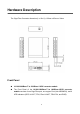
Hardware Description The Giga Fiber Converter dimension (L x W x H): 120mm x 85mm x 26mm Front Panel 10/100/1000Base-T to 1000Base-LX/SX converter module The Front Panel of the 10/100/1000Base-T to 1000Base-LX/SX converter module consists of one Giga Fiber port, one copper Port (Auto MDI/MDIX), and 6 LED Indicators (SPD, LK/ACT, FDX, Fiber LK/ACT, FDX/COL, and PWR).
3 1 4 2 GVT-4000 3 4 2 1 GVT-4001 (1) RJ-45 Port (2) LED (3) DIP-Switch (4) Fiber Connector Rear Panel The rear panel contains a power socket. This power socket accepts DC9V voltage and minimum 0.7A supplied current.
Ports Copper Port (Auto MDI/MDIX) of 10/100/1000Base-T to 1000Base-LX/SX converter module: The Ethernet ports will auto-sense for 10Base-T, 100Base-TX, or 1000Base-T connections. Auto MDI/MDIX means that you can connect to another Switch or workstation without changing non-crossover or crossover cabling. Fiber Port: This port is for 1000Base-SX with SC connections. LED Indicators There are 6 diagnostic LEDs located on the Front panel of converter module.
Amber Full-duplex mode Off Half-duplex mode or link down Green Link up Blinks Transmitting Off Link down Amber Full-duplex mode Off Link down FDX (UTP) LNK/ACT (Fiber) FDX/COL (Fiber) DIP-switch The DIP-switch is used to configure operation mode for LLF (Link Loss Forwarding) and operation mode for Copper/Fiber port. The default value of Dipswitch is OFF.
but instead it forwards the received data immediately after the data being received. And TP port should be forced at 1000M in this application. When DIP-Switch is in Switch Converter mode (off), the converter function is same as Switch Hub. [Note] a) Please don’t change the DIP-switch setting when copper or fiber port is transmitting or receiving data. It may cause some data error. b) Please power off then power on when you change the DIP-switch setting.
Converters module Installation This installation is only for mounted in converter chassis converter module. You can follow the steps below to install modular converters. A. Remove the blank bracket by rotating thumbscrew counterclockwise. Put the blank bracket aside, but don’t discard blanket bracket. B. Open the rack mount ear kit. The kit contains two-rack mount ear (with thumbscrew) and four screws. C.
Cabling Using four twisted-pair, Category 5e cabling for copper port connection. The cable between the converter and the link partner (switch, hub, workstation, etc.) must be less than 100 meters (328 ft.) long. Fiber segment using single-mode connector type must use 9/125 μm single-mode fiber cable. You can connect two devices in the distance of 10 Kilometers in full duplex operation. For half-duplex operation, the recommended maximum distance is 412 meters (1,352 ft.
Troubles shooting Check the configuration DIP-switch. It must be setting in the same operation mode with the link partner. Select the proper Copper/Fiber cable to construct your network. The single-mode converter must use single-mode fiber cable. Please check that you are using the right cable. Don’t both use multi-mode and single mode. Link loss Forwarding problem : When using a mixture of GVT-4000 / 4001 Hardware versions 1 and 2, please note the differences in the dip switches.