
Specification

Vizia +
®
Commercial Grade Lighting Controls Collection
Leviton Mfg. Co., Inc.
201 North Service Road Melville, NY 11747 Tech Line: 1-800-824-3005 Fax: 1-800-832-9538 www.leviton.com
© 2014 Leviton Manufacturing Co., Inc. All rights reserved. Subject to change without notice.
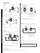
WIRING DIAGRAMS
Hot (Black)
Neutral (White)
Load
Dimmer
BK
Black
White
RD
Green
Ground
Line
120VAC, 60Hz
YL/RD
Use Terminal or wire for 3-way
or More Applications Only.
For Single Pole Applications,
Do Not Remove This Label.
Dimmer
Insulating
Label
Hot (Black)Black
Black
Line 120VAC,
or 277VAC
60Hz
Neutral (White)
Red Yellow/Red
White
White
Green
Ground
06-WIR DIA 4a.eps FILE NAME
Load
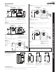
Hot (Black)
Neutral (White)
Load
Dimmer
Coordinating Remote
(no LEDs)
YL/RD
YL/RD
RD
WH
RD
BK
BK
Black
Do not use for
incandescent
applications.
White
Line
120VAC, 60Hz
Green
Ground
Green
Ground
VZI06-WIRING DIA 2-B copy.eps FILE NAME
Coordinating Remote
(no LEDs)
Black
Line
120V
AC
60Hz
Neutral (White)
Red
Yellow/Red
Green
Ground
Dimmer
Black
Red Yellow/Red
Green
Ground
Load
Hot (Black)
Neutral (White)
Dimmer
Coordinating Remote
(no LEDs)
YL/RD
Yellow/Red
RD
White
Red
Black
Black
BK
WH
White
Line
120VAC,
Green
Ground
Green
Ground
(unused)
(unused)
Load
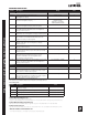
Dimmers
VPI06
VPM10
NOTES:
1) VPI06 has screw
terminals, VPM10
has leads
2) Red and Black leads
(or terminals) are
interchangeable
Dimmers
VPE06
VPX10
VPX12-7L
Dimmers
VPI06
VPM10
Dimmers
VPI06
VPM10
Dimmers
VPE06
VPX10
Fan Speed Control
VPF01
Switch
VPS15
Fan Speed Control
VPF01
Switch
VPS15
Coordinating Dimmer Remote
VP00R-10
Coordinating Switch Remote
VP0SR-10
Coordinating Dimmer Remote
VP00R-10
Coordinating Switch Remote
VP0SR-10
Coordinating Dimmer Remote
VP00R-10
Coordinating Switch Remote
VP0SR-10
NOTES:
1) VPS15 has screw terminals, VPE06, VPX10, VPF01 and VPX12-7L have leads
NOTES:
1) VPI06, VP0SR-10 and VP00R-10 have screw terminals, VPM10 has leads
2) Black connections are interchangeable (see Diagram 4)
3) Silver terminal on coordinating remote is unused
NOTES:
1) VPI06, VP0SR-10 and VP00R-10 have screw terminals, VPM10 has leads
2) Black connections are interchangeable (see Diagram 3)
3) Silver terminal on coordinating remote is unused
NOTES:
1) VPS15, VP0SR-10 and VP00R-10 have screw terminals, VPE06, VPX10 and
VPF01 have leads
2) Black and Red terminals on coordinating remotes are unused
Diagram 1
Single pole wiring for incandescent or magnetic low voltage dimmer.
Diagram 4
Alternate 3-way wiring for incandescent or magnetic low voltage
dimmer with coordinating remote.
Diagram 5
3-way wiring for electronic low voltage dimmer, Mark 10
®
Powerline
dimmer, fan speed control or switch with coordinating remote.
Diagram 2
Single pole wiring for electronic low voltage dimmers, Mark 10
®
Powerline dimmers, fan speed control or switch.
Diagram 3
3-way wiring for incandescent or magnetic low voltage dimmers
with coordinating remote.
Sharing a neutral wire may cause flickering or other unforeseen issues.
Connect all lighting/fan speed controls to the same phase or run a separate
neutral to each phase. Consult the Leviton tech line if problems persist.