
Installation Manual

Series
Series 1000 and Series 2000 Installation Manual
Leviton Manufacturing Co., Inc. 12
3.3 Preparation
1. Verify the model number and electrical specifications of the device being installed to
confirm they are appropriate for the intended electrical service (see Section 2).
2. Consult local codes for any possible permits or inspections required before beginning
electrical work.
3. Ensure the conduit for the installation is appropriate for the intended application. UL Type
4x conduit and conduit fittings required for outdoor applications.
4. Make sure all tools to be used during installation have proper insulation ratings.
5. Look at the Meter and inside the electrical panel for possible exposed wire, broken wire,
damaged components or loose connections.
3.4 List of Materials
Series 1000 or Series 2000 meter, enclosure and associated mounting materials
Line 1, Line 2, Line 3 and Neutral hook-up wires as needed for the electrical service.
Wires must be 18 AWG or larger and insulated for 600 VAC min.
Current Transformers (CTs): This product is designed for use with Leviton CTs
Conduit and fittings as appropriate. UL Type 4X conduit and fittings must be used for
outdoor applications to maintain the rating of the installation.
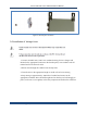
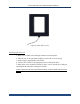
3.5 Mounting the Enclosure
3.5.1 Selecting a Mounting Location
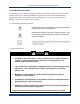
Series 1000 and 2000 meters require a switch or circuit breaker as part of the building
installation.
The switch or circuit breaker must be marked as the disconnecting device for the
meter.
It is recommended that the enclosure be mounted near the disconnecting device in an
area with adequate ventilation.
The enclosure should not be positioned in a manner that makes it difficult to operate
the disconnecting device.
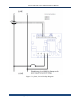
Ensure that the CT and voltage lead lengths (and conduit lengths) are capable of
reaching the enclosure from the load center.
If a suitable mounting location near the load center cannot be found, additional in-line
fuses or circuit breaker may be required in accordance with NEC regulations.