
Installation Manual


Series
Series 1000 and Series 2000 Installation Manual
Leviton Manufacturing Co., Inc. 20
3.8 Testing the Installation
Testing Voltage
Voltage should also be tested using an AC Voltmeter to verify that the voltage
across voltage line terminals (L1, L2, and L3 to Neutral) is not in excess of the
maximum rated voltage.
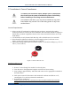
CT Reverse Phase Indicator
Series 1000 and Series 2000 meters have a red reverse phase indicator LED as
described in section 2.3. There must be a load drawing a minimum of 1 A
connected to the meter in order for the reverse phase LED to function
correctly. If this LED is on (with sufficient load), power down the voltage supply
and verify that CTs are installed correctly.
Load LEDs
The load LEDs are described in section 2.3. These LEDs should be pulsing at
50% duty cycle when the meter is connected properly and a constant load is
applied. Without a proper load, the load LEDs could be on or off.
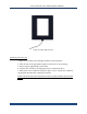
LCD Display
The Series 1000 and 2000 display is described in Section 2.4. From this
description, it is possible to determine if the kWh and/or demand values
displayed on the LCD are consistent with the applied load. A load must be
applied for the kWh value to show significant changes.
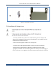
3.9 Securing the Enclosure
In accordance with safety requirements, enclosures must be secured using the
provided key lock once installation is complete. The purpose of the lock is to
prevent access to live parts that pose potential safety risks. To install the lock,
slide through the provided holes on the clamp side of the enclosure and fasten
securely.